12F629
12F675
16C84
16F627
16F628
16F630
16F676
16F72
16F73
16F74
16F76
16F77
16F818
16F819
16C84
16F84
16F84A
16F87
16F88
16F870
16F871
16F872
16F873(A)
16F874(A)
16F876(A)
16F877(A)
18F1220
18F1320
18F242
18F248
18F252
18F258
18F442
18F448
18F452
18F458
18F4320
16F877 asynchronous communication
For non-embedded programmers the first thing to try on a new system or in a new programming language is to print out "hello world". The equivalent for microcontrollers and other embedded systems is to blink a LED. When even the target circuit and the programmer are freshly put together it is wise to start even lower, with a blink-a-LED program written by someone else that is known to be working. Then when the LED does not blink (which is likely) there is one thing less to doubt about. On this page you will find 1 and 2 Hz blink-a-LED (and some other) test programs for various targets chips and circuits. Two blink frequencies are provided so you can check whether a target that already contains one of the blink programs is realy reprogrammed by using the other one.
When you are new to PICmicro controller use, do read my Start With PICs document, before you attempt to use a PICmicro controller.
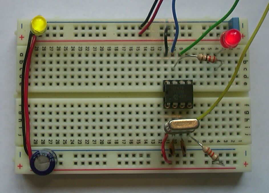
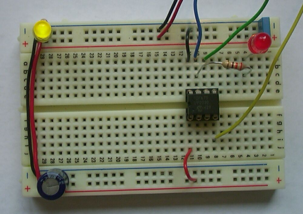
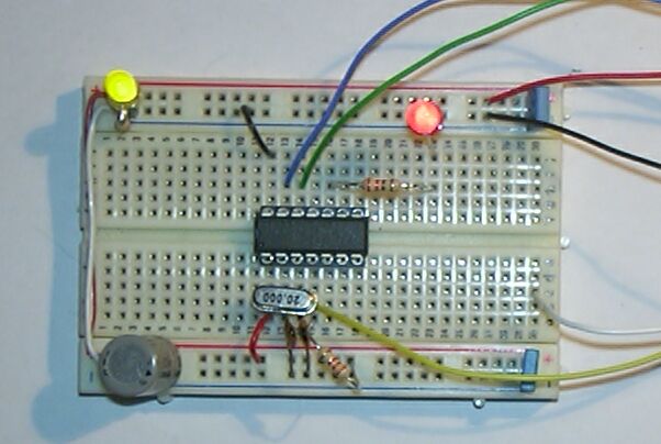
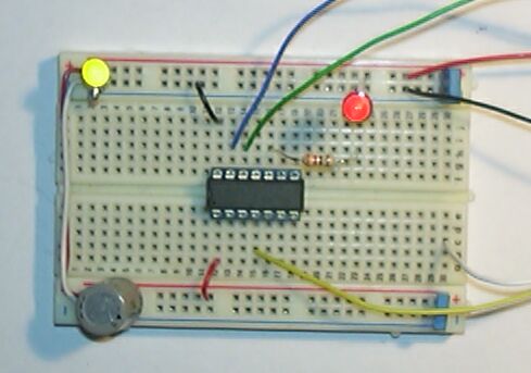
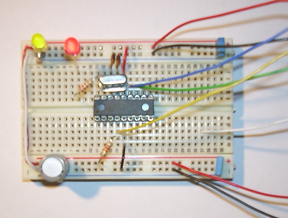
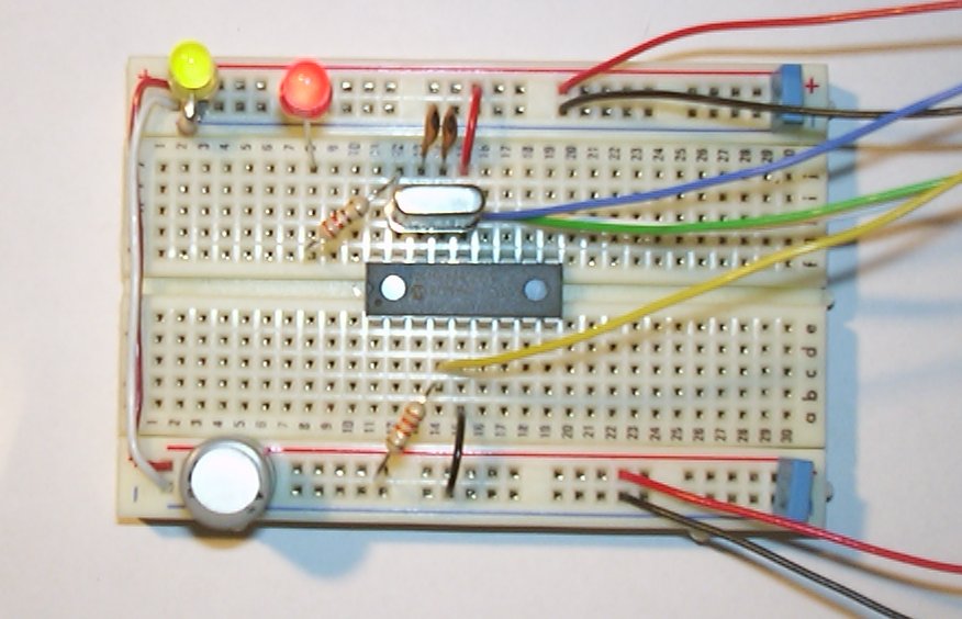
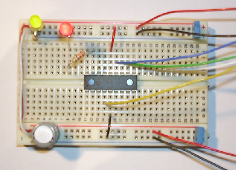
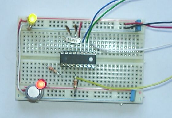
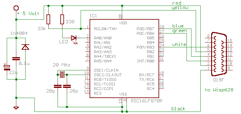
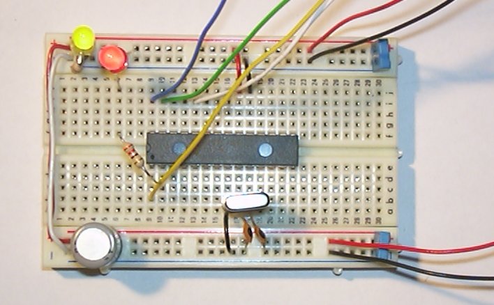
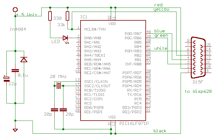
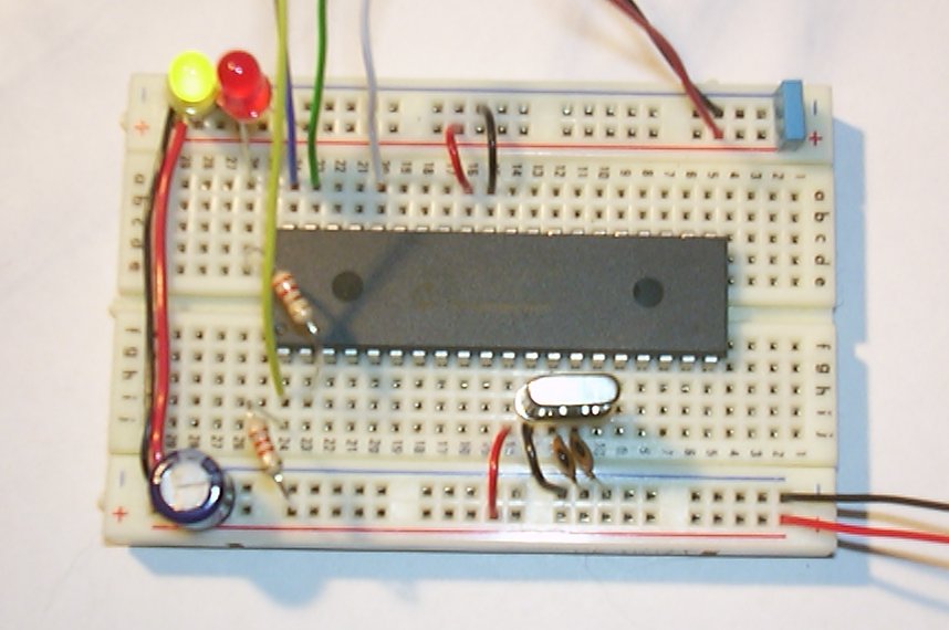
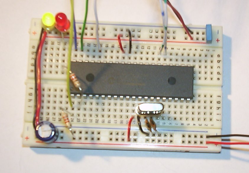
Looking closely at the breadboard pictures you will notice a few components that are not show in the circuit diagrams: a resistor / LED to indicate power, and some extra power decoupling.
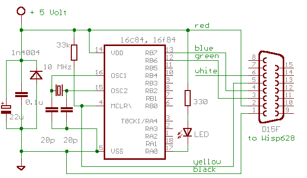
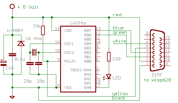
The colors of the wires that connect the programmer to the target breadboard and the corresponding explantion are as advised for use with my Wisp628 programmer. Note that recent kits use a purple wire for what used to be the green wire (RB6). All pictures on this page still show a green wire.
If are looking for other (mostly non-PIC) LED blink, flash and sequencing circuits look here.
| source | b675-1.jal, b675-2.jal | xwisp command line |
python xwisp.py go b675-1.hex
(or go b675-2.hex) |
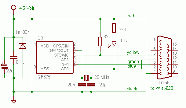
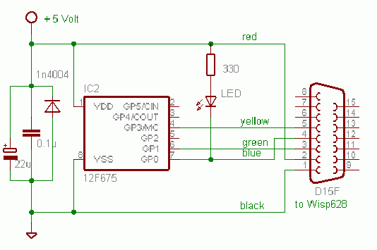
The 12F629 and 12F675 are currently the only 8-pin flash PICmicro chips available. The price of these chips makes them very attractive for small projects. These chips do not support LVP, so pin 6 of the target connector (white wire) can be left unconnected.
| source | b675i-1.jal, b675i-2.jal | xwisp command line |
python xwisp.py go b675i-1.hex
(or go b675i-2.hex) |
The 12F chips have an internal 4 Mhz oscillator and can be configured for internal /MCLR, which reduces the number of external components, and makes more pins available for I/O (with internal oscillator and internal /MCLR 6 I/O pins are available). Note that the internal 4 MHz clock is sufficiently accurate for blinking a LED, but just barely adequate for reliable asynchronous serial communication.
| source | b630-1.jal, b630-2.jal | xwisp command line |
python xwisp.py go b630-1.hex
(or go b630-2.hex) |
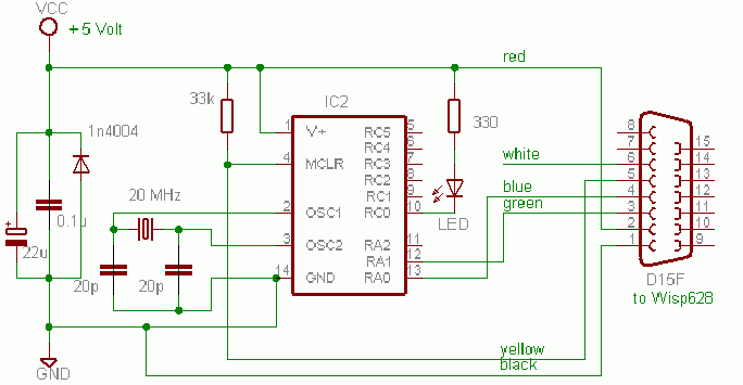
The 16F630 and 16F676 are currently the only 14-pin flash PICmicro chips available. The price of these chips makes them very attractive for small projects, that need some more I/O pins that provided by the 8-pin chips. These chips do not support LVP, so pin 6 of the target connector (white wire) can be left unconnected. Note that (unlike other chips) the 16F630 and 16F676 use RA0 as one of the programming pins. Hence the circuits connect the LED to pin RC0. The programs blink both RC0 and RA0, but connecting a LED to RA0 will make in-circuit programming with Wisp628 impossible because the load is too high for the programmer.
| source | b630i-1.jal, b630i-2.jal | xwisp command line |
python xwisp.py go b630i-1.hex
(or go b630i-2.hex) |
The 16F630 and 16F676 chips have an internal 4 Mhz oscillator and can be configured for internal /MCLR, which reduces the number of external components, and makes some more pins available for I/O. Note that the internal 4 MHz clock is sufficiently accurate for blinking a LED, but just barely adequate for reliable asynchronous serial communication.
| source | b84-1.jal, b84-2.jal | xwisp command line |
python xwisp.py target C84 go b84-1.hex
(or go b84-2.hex) |
The 16C84 and 16F84 are obsolete (and no longer produced by Microchip), but can still be found in published designs. Unlike the other supported PICmicro's these chips have a maximum clock frequency of 10 Mhz. These chips do not support LVP, so pin 6 of the target connector (white wire) can be left unconnected.
| source | b84a-1.jal b84a-2.jal | xwisp command line |
python xwisp.py target f84a go b84a-1.hex
(or go b84a-2.hex)
|
The 16F84A is still produced, but for new designs it obsoleted by the cheaper and more powerfull 16F628. Unlike the 16C84 and the plain 16F84 (without the 'a') the maximum clock frequency is 20 MHz. This chip does not support LVP, so pin 6 of the target connector (white wire) can be left unconnected.

| for 16F62x | source | b628-1.jal b628-2.jal | xwisp command line |
python xwisp.py go b628-1.hex
(or go b628-2.hex)
|
| for 16F81x, 16F8x | source | b818-1.jal b818-2.jal | xwisp command line |
python xwisp.py go b818-1.hex
(or go b818-2.hex)
|
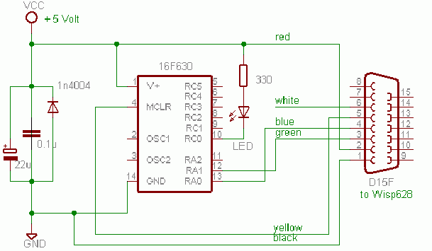
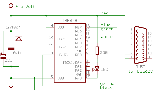
The 16F628 is the cheapest 18-pin flash PICmicro (disregarding the 16F627, which has half the code size but is only marginally cheaper - in fact it is sometimes more expensive). The 16F818 and 16F819 are 18-pins chips with A/D converter (which the 16F62x do not have), but without the UART (which the 16F62x do have).
| for 16F62x | source | b628i-1.jal b628i-2.jal | xwisp command line |
python xwisp.py go b628i-1.hex
(or go b628i-2.hex)
|
| for 16F81x, 16F8x | source | b818i-1.jal b818i-2.jal | xwisp command line |
python xwisp.py go b818i-1.hex
(or go b818i-2.hex)
|
The 16F62x and 16F81x have an internal oscillator (4 MHz fixed for the 16F62x, 32 kHz .. 8 MHz configurable for the 16F81x) and can be configured for internal /MCLR, which reduces the number of external components, and makes more pins available for I/O. Note that the internal 4 MHz clock is sufficiently accurate for blinking a LED, but not for reliable asynchronous serial communication.
| source | b452-1.jal b452-2.jal | xwisp command line |
python xwisp.py go b452-1.hex
(or go b452-2.hex)
|
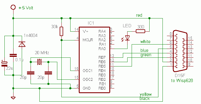
The 18F1220 and 18F1320 are the smallest (and cheapest) members of the 18F family. These are 18-pins chips, but the pinout differs subtly from the 18-pins chips in the 16F family. The blink code is the same as for the bigger 18Fxxx chips. These chips can also run on an internal clock.
| for 16F7x | source | b77-1.jal b77-2.jal | xwisp command line |
python xwisp.py go b77-1.hex
(or go b77-2.hex)
|
| for 16F87x(A) | source | b877-1.jal b877-2.jal | xwisp command line |
python xwisp.py go b877-1.hex
(or go b877-2.hex)
|
| for 18F2xx(A) | source | b452-1.jal b452-2.jal | xwisp command line |
python xwisp.py go b452-1.hex
(or go b452-2.hex)
|
These 28-pin chips can all be regarded as cheaper, stripped-down 16F877(A)'s or 18F2xx's. The blink program for the 16F87x (with or without the A) chips is the same as for the 16F877 itself, for the 16F7x and the 18F25x the program is slightly different.
Note for 18F2xx: the LVP wire (white) must be connected to RB5 instead of RB3 (for the breadboard: next to the purple (used to be green) wire).
| for 16F7x | source | b77-1.jal b77-2.jal | xwisp command line |
python xwisp.py go b77-1.hex
(or go b77-2.hex)
|
| for 16F87x(A) | source | b877-1.jal b877-2.jal | xwisp command line |
python xwisp.py go b877-1.hex
(or go b877-2.hex)
|
| for 18Fxxx(x) | source | b452-1.jal b452-2.jal | xwisp command line |
python xwisp.py go b452-1.hex
(or go b452-2.hex)
|
The blink program for the other 40-pin 16F87x chips (with or without the A) is the same as for the 16F877 itself, for the 16F7x and the 18Fxxx(x) the program is slightly different.
Note for 18Fxxx(x): the LVP wire (white) must be connected to RB5 instead of RB3 (for the breadboard: next to the purple (used to be green) wire).
| source | a877.jal | xwisp command line |
python xwisp.py go a877.hex tty 1200
|
This program repeatedly sends "hello world\n" using asynchronous serial communiacation at 1200 baud, 8 data bits, no parity, 1 stop bit. Pin B7 is used as output, (using true polarity) so Wisp628's passthrough feature can be used to show the message.
| source | a877-b6t.jal | xwisp command line |
python xwisp.py go a877-b6t.hex tty 1200
|
This program waits for an asynchronous serial character, and the echoes the character, and the hexadecimal and binary value of the character. Again Pin B7 is used as output, (using true polarity) so Wisp628's default passthrough feature can be used to show the message. For inverted polarity (for use with a max232) use a877-b6i.jal or a877-b6i.hex
| source | a877-c6i.jal | xwisp command line |
python xwisp.py go a877-c6i.hex tty auxi 1200
|
This program is like the previous one, but it uses the UART pin C6 as output, using inverted polarity (like the UART does, for use with a MAX232 or another inverting driver).
http://www.voti.nl/blink
Copyright (c) 2003 Van Ooijen Technische Informatica / Wouter van Ooijen
Permission is granted to copy, distribute and/or modify this document under the terms of the GNU Free Documentation License, Version 1.2 or any later version published by the Free Software Foundation; with no Invariant Sections, no Front-Cover Texts and no Back-Cover Texts. A local copy of version 1.2 of the license can be found here.