WWPSU : Wall Wart PSU Kit
|
|
WWPSU : Wall Wart PSU Kit |
|

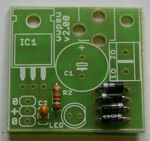
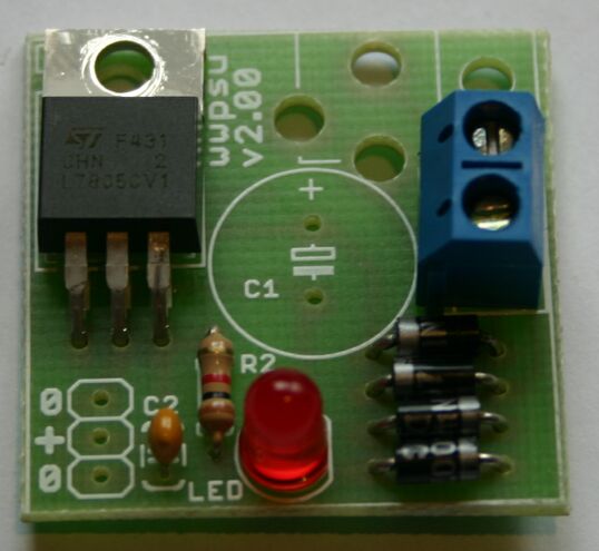
The circuit is very simple: the AC or DC from the Wall Wart connected to the board by the power plug or the screw connector. It is rectified by the four diodes D1 .. D4 and fed into the buffer elco C1. The 7805 voltage regulator converts the rippling voltage on the buffer elco into a clean 5 Volt. A LED with a resistor provide visual indication that power is present (and that the output is not accidentally shorted). The small capacitor C2 at the output of the 7805 stabilizes the regulator.
I assume you know how to solder a PCB. Be patient, don't use too much solder and check your work under a strong lamp (a magnifying glass might be handy).
You can click on each of the pictures to get a larger picture.
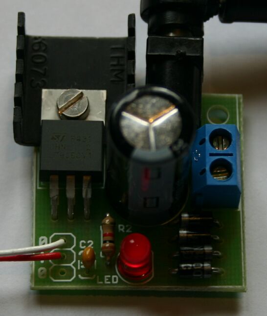
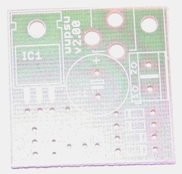
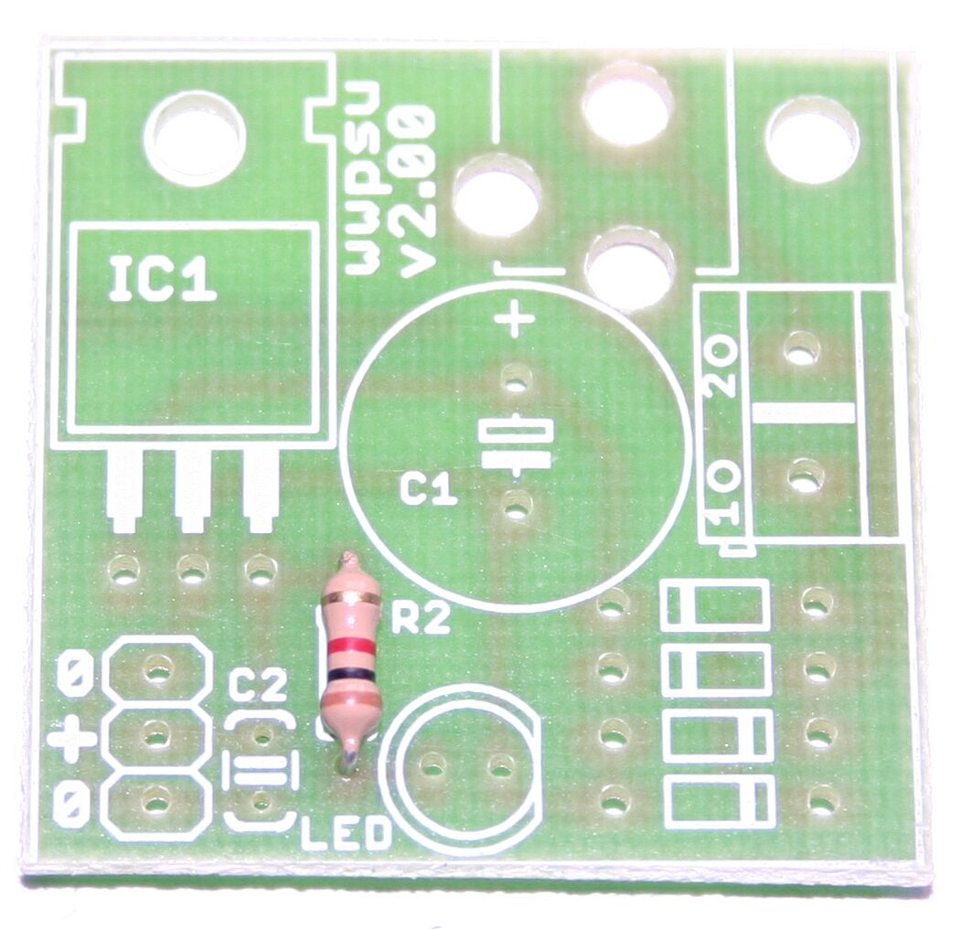
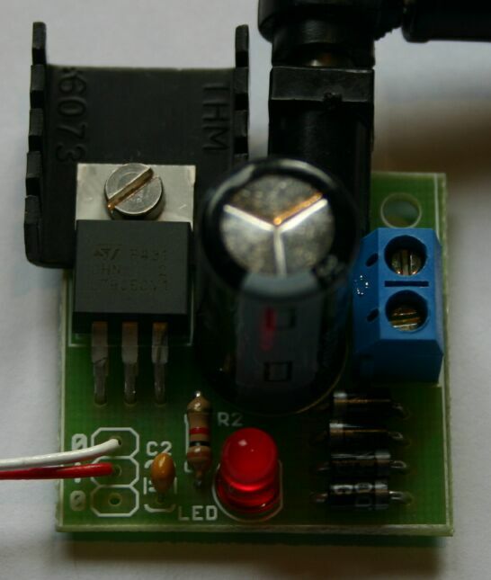
| The description assumes that you have the board oriented as shown, so you can read the component designations on the silkscreen (component) side. |
|
|
| Place and solder resistor R2. I don't know why I called it R2, it is the only resistor in the circuit. |
|
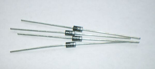
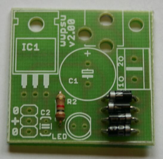
| Place the four 1N4004 diodes D1, D2, D3 and D4. Note the white bands: the top two must face left, the bottom two must face right. |
|
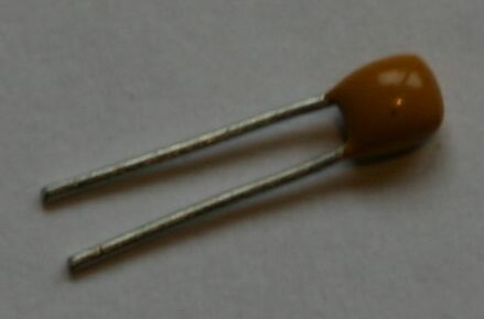
| Place and solder the small capacitor C2. |
|
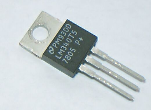

| Place the 7805 IC1, Solder the 7805. Remove the screw and put the heat sink aside for the moment. |
|
|
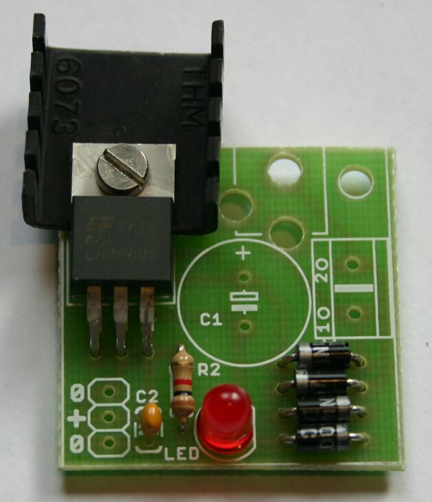
| Place the LED. (Yes I know, this is the same picture as the one above..) The longer tail must be at the left side (away from the diodes). Solder the LED. |

|
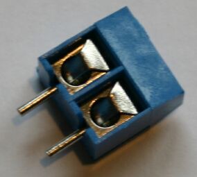
| Place and solder the screw terminal X1, open side down (towards the edge of the board). |
|

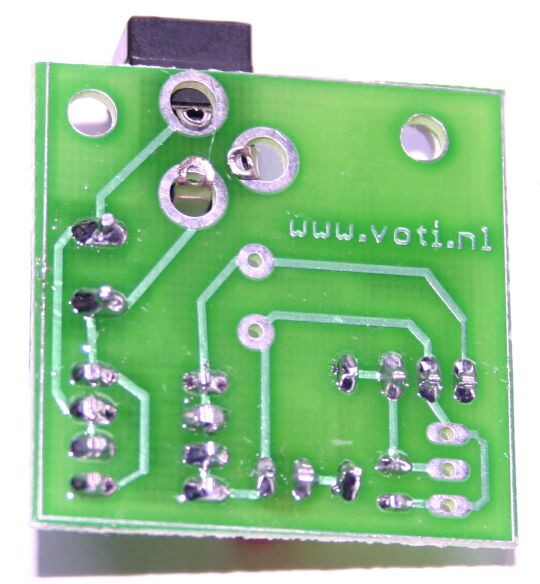
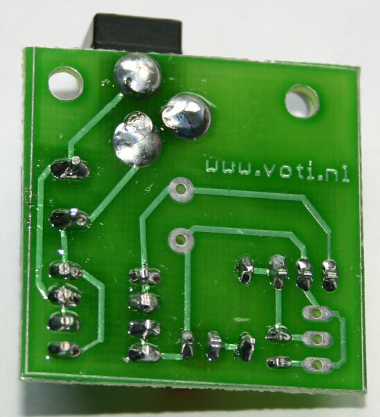
| Place the power connector. At the bottom of the board, bent the solder lugs towards ecah other, flat against the board. A screwdriver will be handy. Now solder the lugs. Use ample solder. |
|
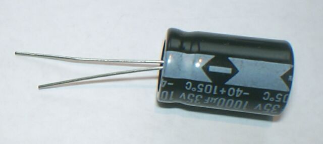
| Place and solder the big capacitor C1. The white stripe must be at the lower side (towards the LED). Fasten the heat sink between the 7805 and the PCB using the screw and bolt. |
|
This circuit will work with any Wall Wart that provides either 7 .. 24 Volt AC or 8 .. 32 Volt DC. The 7805 is both short-circuit and thermally protected, so it is difficult to damage. If you want to draw substantial current you should use a Wall Wart with low voltage (7 V AC or 8 V DC), and/or put a larger heat sink on the 7805 than the one provided in the kit. With the provided heat sink the 7805 can dissipate at least 3 Watt.
The input is provided by the screw terminal or the power connctor, your choice. The power connector might be most convenient, but for a sturdy connection the screw terminal will be better. The input is rectified, so for a DC Wall Wart it does not matter how the + and - leads are connected. The 5 Volt output is provided on the three unused holes at the left of the PCB. The two outer holes are at ground (0 Volt), the inner is at + 5 Volt.
http://www.voti.nl/wwpsu
Copyright (c) 2002, 2006 Van Ooijen Technische Informatica / Wouter van Ooijen