
Stepbots
last modified 27-APR-2000Wouter van Ooijen (wouter@voti.nl)

|
|
Stepbotslast modified 27-APR-2000Wouter van Ooijen (wouter@voti.nl) |
|
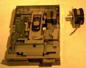
I have build a number of stepbots: small PIC-controlled robot vehicles using stepper motors. The basic idea is to use two steppers which are directly connected to the front wheels, and a real wheel which can turn freely. The two steppers take care of the propulsion and steering. The steppers from old 5.25 disk drives are very practical, requiring 100 mA (per coil) at 12 Volt, which can be provided by 10 penlight NiCads. A 7805 regulator provides the 5 Volt required for the PIC 16f84 brain. A single ULN2803 interfaces the brain to the two stepper motors. I use either a 24 Volt wall wart to charge the NiCads and series resistor in the robot that selects the appropriate charge current, or a removeable NiCad pack.
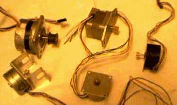
5.25 inch diskdrives contain a number of different stepper motor types. You can find steppers with 4, 5 and 6 wires. The 4 wire types (often found in the more recent 5.25 drives) are bipolar and can not be used with the circuit described here. The 5 and 6 wire types are essentially the same. Use an multimeter to find the one (5 wire steppers) or two (6 wire steppers) common wire(s) that have a low resistance to other wires. For a 6 wire stepper connect the two commons together and you have a 5 wire stepper.
Now you must find out the stepping sequence. You can do this by hand, using a 12 V power supply (watch out for the spikes when you remove the power from a coil!), or by connecting the stepper to the robot circuit programmed for continous motion. In both cases you must find the correct sequence by trial and error, but you can keep one coil fixed, and from the remaining 8 possibilities two are OK (one for forward and one for backward motion).
The front wheels are taken from broken office chairs. These wheels are a bit difficult to take apart, but a combination of patience and some brute force will do the job. I drill a hole through the center of each half wheel which is a little bit smaller than the metal cylinder on the steppers' shaft and use some force to push it onto the shaft. A strip of self adhesive staircase grip paper around the wheels improves the grip on smooth undergrounds.
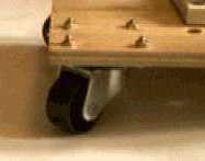
The real wheel is a swivel wheel, the kind used under office chairs and TV trolleys. It is important that the real wheel turns easily, which requires that it has a very small area of contact with the underground, and that this area is only a tiny bit (a few mm) behind its vertical axis. The wheel on the left picture is much better than the one on the right. An alternative real 'wheel' is a smooth sphere that simply sits beneath the real of the stepbot.
|
|
The brain of the robot is a Microchip PIC 16f84 microcontroller. This chip not very expensive, has enough horsepower for this simple control task and can be programmed quickly without removing it from its circuit. I use either a test clip directly on the chip, 2x3 pin header (one pin cut off as key) or a D15M connector as in-circuit programming interface. The electronics (16f84, crystal, 7805, ULN2803 and a few pin header connectors) can be build on a 2 x 3 cm breadboard.
Don't expect miracles from this simple hardware: it can crawl for an hour or so at its top speed of a few cm per second provided that the underground is smooth and level. The steppers deliver just enough power to move the vehicle, so it will not ride over any substantial obstacle. A toothpick in its path can be enough to block it.
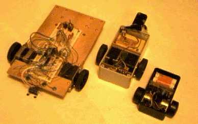
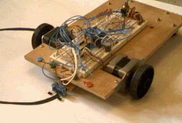
The three stepbots shown below use essentially the same hardware. The first (left) one was build on a piece of wood using a solderless breadboard for easy modification. A battery pack can be put on its back. The middle one has its electronics (on a small PCB), the two steppers and a battery pack in a small gray case. Both use 12V steppers from 5.25 inch drives. The right one uses smaller 5V steppers from a small printer. It is not succesfull because the steppers do not deliver enough pull and I could not find a suitable rear wheel.
The essence of a simple Jal program to move the robot is shown below. The delay can be varied to find the minimal step interval which can start the robot. The library procedure stepper_motor_full_forward produces the sequence 0001, 0010, 0100, 1000. Similar procedures are available for half stepping and for stepping backward. The initial values can be changed to 0b_0011 to get a two coil sequence.
   -- a robot that just rides at a constant speed
   include 16f84_10                         -- define target
   include jlib                             -- standard libraries
   var byte left    = 0b_0001               -- start of the stepper sequences
   var byte right   = 0b_0001               -- "
   port_b_direction = all_output            -- an input would not help us much
   forever loop                             --
      stepper_motor_full_forward( left )    -- step both sides forward
      stepper_motor_full_forward( right )   -- "
      port_b_low  = left                    -- output the new steps
      port_b_high = right                   -- "
      delay_1mS( 25 )                       -- 25 mS delay between steps
   end loop
A more interesting but still very simple robot follows a line on a piece of paper. I use a black line on white paper. The line is approximately 5 mm wide. The robot is placed on the line before it is started. The main problem is to follow a line which bends abruptly. One sensor could be used, but this requires the robot to sweep left and right to keep locked onto the line. I used two (reflective) sensors.
   -- a robot that follows a line using two sensors
   include 16f84_10                              -- define target
   include jlib                                  -- standard libraries
   var bit left dark at pin_a0                   -- define IO pins
   var bit right_dark at pin_a1                  -- "
   var byte left  = 0b_0001                      -- start of the stepper sequences
   var byte right = 0b_0001                      -- "
   port_b_direction = all_output                 -- IO direction
   port_a_direction = all_input                  -- "
   forever loop                                  --
      if ! left_dark then                        -- when left sensor sees white
         stepper_motor_full_forward( left )      -- step left motor
      end if                                     --
      if ! right_dark then                       -- when right sensor sees white
         stepper_motor_full_forward( right )     -- step right motor
      end if                                     --
      port_b_low = left                          -- output the new steps
      port_b_high = right                        -- "
      delay_1mS( 25 )                            -- 25 mS delay between steps
   end loop
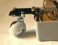
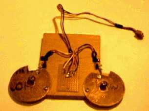
Maze walking is more impressive than line following but also more difficult. (apart from the fact that you will also have to build a maze!). Any connected maze can be walked by following the wall with your left (or right) hand. Using switches to detect collision with a wall seems simple until you try it. A wall will always turn up at an unexpected angle, so a lot of switches are needed or a clever mechanism must allow a switch to be pushed from a wide range of angles. My robots do not have much power, so the switch must also be easy to push. I made a wide angle mechanism from a round piece of PCB material (I would have preferred a flippo but I could not find one). An obstacle in front or to the side of the robot will turn the circle around its axis, closing the switch. This works fine but the robot must keep close to the wall which makes a closed turn difficult and an irregular wall can lock the robot into a corner. A wire sensor like a cockroaches' antenna would probably not have these problems. The things on the picture below that look like Mickey Mouse ears are PCB pieces. The switches have been salvaged from an old VCR.
The most critical part of the software for my maze walker is the part which controls the turning, especially when it must turn left after it has hit its nose against a wall. The software uses feedback from the switches as often as possible to compensate for possible slip between the wheels and the surface. A turn right must not start too soon because the robot would get stuck against the edge of the maze (the sensor is in front of the turning axis of the robot). Apart from these two difficult turns the software just makes the robot follow the wall to its right side. When it senses the wall it steers away from the wall, when it does not sense the wall it steers (a little bit) to the right where it expects the wall. If the wall is lost for a significant time it turns to the right.
   -- a maze-walking robot that follows the wall to its right side
   include 16f84_10
   include jlib
   var volatile bit  right_free  is pin_a3
   var volatile bit  left_free   is pin_a4
   var volatile byte left_motor  is port_b_low
   var volatile byte right_motor is port_b_high
   const byte stepper_initial    = 0b_0011
   var byte left_value           = stepper_initial
   var byte right_value          = stepper_initial
   port_b_direction              = all_output
   port_a_direction              = all_input

   procedure move( byte in left, byte in right ) is
      while ( left != 0 ) | ( right != 0 ) loop
         if  ( left != 0 ) then
            if left < 128 then
               stepper_motor_full_forward( left_value )
               left = left - 1
            else
               stepper_motor_full_backward( left_value )
               left = left + 1
            end if
         end if
         if ( right != 0 ) then
            if right < 128 then
               stepper_motor_full_forward( right_value )
               right = right - 1
            else
               stepper_motor_full_backward( right_value )
               right = right + 1
            end if
         end if
         left_motor  = left_value
         right_motor = right_value
         delay_1mS( 25 )
      end loop
   end procedure

   var byte n     = 0
   forever loop
      -- frontal hit : turn left
      if ! left_free then
         -- move back to get free from the wall
         move( -100, -100 )
         -- turn a little bit left
         move( 0, 30 )
         for 3 loop
            -- forward until right sensor hits
            while right_free loop move( 1, 1 ) end loop
            -- a little bit back to get free from the wall
            move( -10, -10 )
            -- turn right until left sensor hits
            while left_free loop
               move( 1, 0 )
               move( 1, -1 )
               move( 1, 0 )
            end loop
            -- retreat to make toom for the turn left
            move( -90, -90 )
            -- turn left
            move( -30, 30 )
         end loop
         -- retreat to make toom for the turn left
         move( -15, -15 )
         -- turn slowly left until right sensor hits
         for 75 loop move( 1, 3 ) end loop
      -- hit right wall
      elsif ! right_free then
         -- remember & steer away
         n = 0
         move( 1, 2 )
      -- free on both sides
      elsif ( n < 120 ) then
         -- turn a little to the right
         n = n + 1
         if ( n & 3 ) == 0 then
            move( 1, 0 )
         else
            move( 1, 1 )
         end if
      -- definitely lost the wall
      else
         -- turn right sharply
         move( 1, -1 )
      end if
   end loop
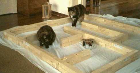
The Mickey Mouse robot can walk a maze by following the wall to its right side, but it has its problems. It can get stuck in a corner, it sometimes thinks it must turn right when it actually just wandered a little bit from the wall, and it must make some strange moves to make a left turn (when runs into a wall). This is largely due to the relatively large distance between the front wheels and the real wheel. But it works! Below you can see it crawling its way through a maze. The cloth is needed because the wheels do not get enough grip on my wooden floor. My cats don't know what to think of this oversized mouse.
 $LEGAL