
|
|
|
|
|
|
|
|
|
|
|
MicroKit is a tool that helps making applications that run bare-metal (without a Operating System) on 32-bit microcontrollers using GNU assembler, C, or C++. Typical targets are ARM7TDMI chips in the NXP (ex-Philips) LPC series.
MicroKit is specifically aimed at the ARM novice. The user can ignore the ugly and chip-specific details like initialisation, timing, and I/O pin configuration. This makes MicroKit suitable for a first course in ARM programming, which is exactly what I use it for. But the advanced user can get full control over such details, should he ever want to.
Developing for an embedded target requires a tool to download your application to the target chip, and probably to debug it. MicroKit offers easy integration with such tools: integrated tools are launched (and if possible, run fully automated) when the application has been compiled and built.
A simple MicroKit application can be very small. It consists of a configuration part and a code part. These parts can be in different files. In that case the configuration part can be like this:
|
The first line configures the library for a This implies configuring for the appropriate chip (an ARM LPC2138), the crystal (12 Mhz), etc. It also makes some library routines available, adapted for this board, like mkt_leds_write. The next line specifies that the application is to be build for loading into ROM (FLASH). The alternative is to load into RAM. The last line specifies the tool to be used to load the application into the target chip, in this case the lpc21isp bootloader.
|
The C part of the application contains just the main function. The debugger automatically sets a breakpoint at the first instruction in the main. To keep this breakpoint out of the main, the first line is the intialisation of a dummy variable. Next is a neverending loop. This loop lights all LEDs, waits one second, blanks all LEDs, waits another second, and starts all over. I prefer the expression 1000 * 1000 over the less readable 1000000 (I can't quickly see whether the number of 0's is correct). The 'return dummy;' will never be executed, but it is required according to the C standard. A pity the standard commitee never realised that an embedded application has nothing to return to.
I prefer to have all aspects of an application in one source text file. MicroKit supports this way of writing programs: all parts of an application (configuration, headers, assembler code, C code, C++ code) can be put in an .mkx file. Using this format the application would look like this:
|
The same example can be coded in ARM assembler. This file is a bit longer, mainly because the loading of a parameter and the subroutine call are on separate lines, and I added white lines to separate the subroutine calls. Otherwise the code is the same.
|
The first two lines declare the 'main' label and make it accessible to other files (alternatively, MicroKit provides the macro to do this is in one line). The body of the main consists of four pairs of lines. The first line of each pair loads R0 with an appropriate value, the next line calls a subroutine. The last line ('b main') jumps back to the start of the main.
MicroKit has a number of limitations. When your application's needs surpasses these limitations MicroKit is probably not a good choice for you.
|
PC/Windows (XP, Vista) only.
|
|
ARM only.
|
|
No C libraries.
|
|
No dynamic memory management.
|
|
Limited range of chips and boards.
|
|
static choice of fast or slow GPIO.
|
|
static choice of clock speeds
|
|
limited range of tools and interfaces
|
|
MicroKit can be used from a command line, but most users will probably prefer an Integrated Development Environment (IDE). Currently only one IDE is supported: PsPAD. |
|
GCC only
|
|
no exceptions
|
MicroKit should work on Windows XP and Vista machines. To use MicroKit:
|
download and install the ARMDevEnv (to its default location: C:\Program Files\ARMDevEnv) |
|
download and install Python 2.6.2 (to its default location: C:\Python26; it will probably work with other Python versions, including 3.0) |
|
download and install the Python for windows extensions (this is the version for Python 2.6.x, you must use a version that matches your Python version) |
|
download and install the PIL (this is the version for Python 2.6.x, you must use a version that matches your Python version. currently no PIL seems to be available for > Python 2.6) |
|
download mkt.py and put it in the directory where your source file(s) are (as yet there is no install for mkt.py, just copy it to every place where you use it) |
|
download lpc21isp.exe and put it somewhere in your PATH, C:\Program Files\ARMDevEnv\bin would be a good place |
To use MicroKit with the HU ARMDevEnv and the PsPAD editor:
|
make sure you have installed all items as mentioned in Installation |
|
put a copy of mkt.py in the directory where your source file(s) and the pspad .dev file are |
|
Put a copy of the MicroKit Makefile for the ARMDevEnv in the directory. Running the DOS command "mkt.py -pspadfile" in the directory where your sources are will create this Makefile. You must copy this Makefile (and the mkt.py file, and of course a .dev file) to every new directory where you want to create a project. |
|
Now you can double-click on the .dev file and use the PsPAD environment as you did before. Note that clicking the debugger icon will no longer do an automatic build of the project, so you must explicitly do a build first. |
|
The linkerscript and crt0.s files are no longer used. The crt0.s file must be removed from the list of project files (otherwise it would still be included in the project). |
Somewhere in your source files you must specify the configuration information that MicroKit needs. I suggest you do this at the top of the file that contains your main funtion (or subroutine). As a start you can use these lines to run with the Insight debugger as you probably did before:
|
To download your application to ROM you must
|
For assembler code: make sure you have used the appropriate memory directives to put the code and data in the appropriate sections. |
|
Change the "#configure memory ram" directive to "#configure memory rom". |
|
Add a directive like "#configure port COM1", where COM1 is replaced by the actual serial port that your board is connected to. For a real serial port this will likely be COM1, but for an USB-simulated serial port the PC will choose the serial port number. For lcp21isp you must change this number to a number in the range 1..4. I prefer 4. To do this start the Device Manager (start -> Control Panel -> System -> Hardware -> Device Manager). Expand ports (COM & LPT) and double-click on the UBS-serial port. Choose Port Settings -> Advanced. Now you can change the port number to COM4. The PC will probably complain that this port is in use, but if you currently have no COM4 present you can do this safely. Sadly, this setting will be effective only for this particular USB-serial converter, and when plugged into its current USB connection. |
|
Rebuild your application. Click the debugger icon. This will start the lpc21isp downloader. When the downloading is completed your application starts automatically. |
The MicroKit tool itself is a command line application. The simple way to use it directly is to specify the source file(s) that make up your application. The tool will build your application, and (if the build was completed succesfully) download and run it. If you just want to build you can add the "-build" option, if you just want to download and run an application you just built you can use the "-run" option.
If you just want to upload an image file (.bin or .hex) to ROM you can specify that image file (and no source files). In thus case you must also specify at least the chip, xtal frequency and serial port on the command line. Alternatively, you can specify the board, which implicity specifies the chip and xtal frequency:
|
For all source and image files specified on the command line the file extension can be omitted, provided that only one file with a suitable extension is present. This file name cleverness can be disabled by using the option "-noclever".
Microkit does not write anything to the directory it runs from: all temporary files and result files are written to the directory C:\_mkt_temp. In normal use this will not be visible to the user, but it has the benefit that when MicroKit is run from an USB stick (which is normal practice in a classroom) writing to the USB stick (slooooow) is avoided.
People have critisized me for using a fixed temporary directory location. I would like to change this to a system-defined location, but the problem is that I need the real pathname of such a location (in the correct case), and so far I have not found a way to obtain this on Windows. The tempfile.gettempdir() function does return the system-defined temporary directory, but not always in the correct case, it might for instance return C:\TEMP on a system where (only) c: emp exists. If you know how to solve this please let me know!
MicroKit must be configured for the target hardware you use to run your apllication on. The easiest option is to use one of the supported Boards. If you don't, you must configure at least
|
chip: the target chip that you use. Choices are: lcp2106, lpc2148. |
|
xtal: the main crystal that you use. You can use the abbreviation '* MHz' to make this a bit more readable. |
By default the CPU will run the frequency of the crystal. The LPC chips have an on-chip PLL (Phase Locked Loop) circuit that can derive a different CPU clock from the crystal frequency. You can configure this cclk frequency. The startup code will configure the PLL to generate this clock (provided that this is possible).
By default the peripherals in an LPC chip run at a clock that is the same as the CPU clock. Alternatively, you can specify this pclk (peripheral clock) to be half or a quarter of the CPU clock (this saves some power).
You must always specify whether you want the application to be built for ROM (FLASH) or for RAM. When you specify ROM the default download/debug/run tool is lpc21isp at 19.2 Kb. When you specify RAM the default download/debug/run tool is Insight, using a parallel-port wiggler connected to LPT1.
The example configuration below illustrates these options. The first three lines are mandatory, the rest is optional.
|
|
|
The mkt_busy_wait_us routine waits the indicated number of microseconds. The actual wait time can be somewhat higher than the requested time, because the call and preparation overhead is not taken into account, and it is assumed the CPU runs uninterrupted and at full speed (no interrupts, no instruction fetch stalls). On some chips code can rull at full speed from RAM but not from ROM. In those cases the actual delay loop will be placed in RAM.
This function should be used when the code must wait a certain minimum time, for instance to satisfy the timing requirements of an external chip. The library itself uses this function for instance to interface to an HD44780 LCD controller. When timing accuracy is important this function should probably not be used, consider using a hardware timer instead.
The argument is an unsigned 32 bit integer, so the maximum wait time is almost 4295 seconds. If you need a longer wait time I guess you can implement it yourself.
Currently mkt_wait_us is a synonym for mkt_buys_wait_us. When multitasking is implemented, mkt_wait_us will (at its sole descretion) either do a busy wait (as it does now), or ask the multitasker to suspend the current task for the indicated time. Hence the use of mkt_wait_us is to be preferred over mkt_busy_wait_us, unless you realy realy wants a busy wait.
The general-purpose IO pins of a microcontroller can be set (made high or low) and read directly by the processor. This is the most basic way to use an IO pin. When a more complex protocol is implemented in software (the processor is fully responsible for setting the pin direction and values, and for the correct timing) this is often referred to as bit-banging. (As opposed to using build-in hardware, like a UART.)
In the library a general-purpose IO pin is identified by a number, counting from 0 up to the number of available pins. The chip documention often refers to the pins in sets of 32 pins, like P0_0 .. P0_31 and P1_1 .. P1_31, etc. The library indentifies these pins as 0 .. 31 and 32 .. 63.
The pins are often shared between the basic general-purpose IO function and one or more hardware peripherals (UARTs, counters, PWM, etc). To use a pin as basic IO pin it must first be configured as such (as opposed to for instance PWM output), and be set to the correct direction (input or output). After this has been done the pin can be written (made high or low) or read.
On most 32-bit microcontroller the I/O part of the chip runs at 3.3V, but the pins are 5V tolerant: when used as input they accept 0..5V. (But do check the datasheet, and take note: applying > 3.3V to any input pin has been reported to degrade the performance of the A/D converter.)
The library provides a number of services that can be used to manipulate IO pins. The easiest way is to first set the direction, and then write or read the pin, using the functions mkt_pin_direction, mkt_pin_write and mkt_pin_read.
|
N is the number of the IO pin. D is the desired direction (allowed values are mkt_input and mkt_output). V is the value that must be written to the IO pin, conform the C convention for truth values: 0 for low, any other value for high. Likewise mkt_pin_read_read returns 0 when the pin is low, or a non-zero value when the pin is high. A call to both configures the pin as basic IO pin, and sets the direction to input or output, as specified by D. An invalid value for N will cause a call to the fatal error handler.
These very simple code snippets copy pin 0 (input) to pin 1 (output):
|
|
|
|
This function configures the indicated IO pin as basic IO pin and sets the direction as specified by the direction parameter. The allowed values for the direction parameter are mkt_input and mkt_output.
An invalid value for N will cause a call to the fatal error handler.
|
|
This function sets the direction of the indicated IO pin as pecified by the direction parameter. The allowed values for the direction parameter are mkt_input and mkt_output.
An invalid value for N will cause a call to the fatal error handler.
|
|
This function sets the value of the indicated IO pin. A false (zero) value for V makes the pin low (0), a true (non-zero) value makes the pin high (1). An invalid value for N will cause a call to the fatal error handler. The pin must be configure as basic IO pin and as output. Function mkt_pin_configure can be used to do both.
An invalid value for N will cause a call to the fatal error handler.
|
|
This function returns the value of the indicated IO pin. If the pin is low (0) a false (0) value is returned, if the pin is high (1) a true (non-zero) value is returned. The pin must be configure as basic IO pin and as input. The function does both.
An invalid value for N will cause a call to the fatal error handler.
When LEDs are connected to the target chip the function mkt_leds_write can be configured to set the value of the (up to 32) LEDs. The function mkt_leds_init initializes the IO pins for writing to the LEDs, but this function is automatically called by mkt_leds_write when that function is first called, so it is unlikely that this initialisation function must be called explicitly by the application.
The following example produces a KITT style pattern on 8 LEDs:
|
|
|
The function mkt_leds_init initializes the GPIO pins used for accessing the LEDs, but this function is called automatically by mkt_leds_write, when it is first called, so it is unlikely that you will use this function directly.
|
|
The function mkt_leds_write first initializes the hardware for writing to the LEDs (if not done yet) and then writes the value V to the LEDs. Bit 0 of V determines whether LED 0 will be on (a bit value of 0 turns the LED off, a 1 turns the LED on), etc. The bits at positions higher than the number of LEDs are ignored.
The library provides support for a character LCD with an HD44780-type controller. The following example alternates between showing two texts on such an LCD:
|
|
|
The function mkt_clcd_init initialises the GPIO pins used to access the LCD and initialises the LCD itself.
This function is called automatically on the first use of any other character LCD function, so it is unlikely that this function needs to be called directly form the application.
Calling this function does not clear the display nor does it position the write cursor.
|
|
The function mkt_clcd_char_write prints the character c at the current position on the LCD and advances the (invisible) write cursor one position to the right. Characters that would be written beyond the right boundary of the display will be ignored. The cursor does not wrap around to a next line. When the write cursor is outside the visible part of the LCD this function has no effect.
The following characters have a special meaning:
|
'\r' : puts the write cursor at the start of the current line. |
|
'\v' : clears the display and puts the cursor at the top-left position (same effect as calling ()). |
A UART is a Universal Asynchronous Receiver and Transmitter. It is a hardware implementation of the protocol used for instance by the serial port of your PC. Most 32-bit microcontroller chips contain at least one UART. The Library provides support for the basic UART operations: you can initialise the UART, you can check whether the UART is busy transmitting, you can submit a character for transmitting, you can check wether the UART has a (received) character available, and you can retreive a received character. The UART routines do not implement any form of handshaking.
Each UART routine takes as first parameter a pointer to a UART. For UARTs are identified by the library as UART0, UART1, etc.
The example below transmits a message each second at 9600 baud using UART0.
Note that the routine mkt_uart_char_write requires a UART parameter (besides the char which is to be transmitted), hence to use a wrapper function must be declared that is hard-coded for UART0, and takes just a char as parameter.
|
|
|
The function mkt_uart_init initialises the UART for the indicated baudrate and connects the UARTs RxD and TxD functions to the designated I/O pin. The UART will be initialised for 8 databits, 1 stop bit, no partity, no handshaking.
Note: this will disable the GPIO function on the Rx and Tx pins. Check the datasheet of your chip for the I/O pins designated for each UART.
|
|
The function mkt_uart_transmit_busy reports whether the UART is currently transmitting a character.
Two situations where you might need this function are:
|
You want to call mkt_uart_char_write, but you can not tolerate any busy waiting within that function. In this case you will have to check mkt_uart_transmit_busy first, and if it reports true you should not yet call mkt_uart_char_write. |
|
You use an external transceiver that needs to be switched from transmit to receive. After sending the last character you must poll mkt_uart_transmit_busy untill it returns false, and then you can switch the transceiver to receive. |
|
|
The function mkt_uart_char_write sends the char using the UART. This function first waits for the UART to complete transmitting of a previous character. When you can not tolerate this delay you can call mkt_uart_transmit_busy: If that function returns false the mkt_uart_char_write will not incur any extra delay.
|
|
The function mkt_uart_char_available reports whether the UART currently has a received character available for retrieving using mkt_uart_char_get. If you want to read a character from the UART but you can not afford to wait for it (if no character is available mkt_uart_char_get will wait for one) you can first call mkt_uart_char_available to avoid waiting.
|
|
The function mkt_uart_char_get returns a received character. If no character is available it will wait untill one is. The function mkt_uart_char_available can be used to test whether a character is available.
Assembler code that wants to be able to run from ROM must specify how the code and data is to be distributed over RAM and ROM. This section explains how this is done. When you write your code in C or C++ the compiler takes care of placing code and data in the correct segments.
An embedded system uses ROM and RAM. When the application is run from RAM the picture is simple: all elements of the application reside in RAM. When the application runs from ROM the picture is more complicated. RAM is more expensive for the chips manufacturer than ROM, so most chips contain much more ROM than RAM. Hence the use of RAM must be minimized. Code and read-only data (the text segment) generally resides in ROM only. Data that needs no initialization (stack, heap) and data that is initialized to zero (the bss segment) resides in RAM. Data that has a specific initialization value, yet needs to be writeable (the data segment), must be treated special: it resides in RAM, but an image of it is kept in ROM. Before the application itself starts, this image is copied to RAM, and the zero-initialised data (bss segment) is cleared. This is done by the startup code.
When you write your code in C or C++ the compiler takes care of placing code and data in the correct segments. When you use assembler you must manage this yourself. The library provides macros to make this a bit easier (but you must still do the thinking):
|
The macro mkt_code is used before code (instructions, code segment). |
|
The macro mkt_data is used before read-write data that needs has a specific initialization value (bss segment). |
|
The macro mkt_bss is used before zero-initialised data (data segment). |
|
The macro mkt_rodata is used before read-only data (this could equally well be put in the text segment using the mkt_code macro, but a separate macro explains the intention of the programmer more clearly). |
|
A piece of assembler code will often be a subroutine. The macro mkt_subroutine can be useful for this situation because it combines the effect of the mkt_code macro with the declaration of the (externally accessible) subroutine label, and it places each subroutine in a separate section, which helps to reduce the size of the application. |
The mkt_code assembler macro starts an assembler code section. This macro generally expands to:
|
Use this macro before a section that contains assembler code which can be placed in ROM, for instance:
|
The mkt_data assembler macro starts an initialised read-write data section. This macro expands to
|
Use this macro before a data section that has explicit (non-zero) initialisations, for instance:
|
This macro should be used rarely, most data either needs no explicit initialisation (use mkt_bss) or is read-only (use mkt_rodata). When run from ROM a DATA section occupies both ROM and RAM, and when running form RAM it must be loaded at the start of each session. A mkt_bss section occupies only RAM, and need not be loaded (it is initialised to zero by a loop in the startup code). A mkt_rodata section occupies only ROM. Most microcontroller chips have much more ROM than RAM, so it is important to place as much as possible in ROM.
The mkt_bss assembler macro starts a 0-initialised read-write data section. This macro expands to
|
Use this macro before a data section that either needs no initialisation, or must be initialised to zero, for instance:
|
mkt_bss sections occupy only RAM (no ROM) and do not add to the 'startup' time when you are debugging: BSS sections are automatically initialised to zero by a loop in the startup code.
The mkt_rodata assembler macro starts a read-only data section. This macro expands to
|
Use this macro before a data section that will only be read (never written), for instance:
|
When running from ROM mkt_rodata sections occupy only ROM (no RAM). When you are debbuging mkt_rodata sections are downloaded, so they add to the 'startup' time.
Note that mkt_rodata has almost the same expansion as mkt_code, but using a separate macro states the intent of the programmer more clearly.
mkt_subroutine is an assembler macro that can be used to start a section that contains a subroutine. This macro has one parameter, the label (name) of the subroutine. It expands to
.section .text.\label
|
The .section line causes each subroutine to be placed in a unique section. When the linker needs a label, it will include all of the section that contains that label. Without the .section line all subroutines in a source file would be in the same section, so they would all be linked into your application when only one is used. With the .section line only the subroutines that are actually used will be linked, so the size of the application is reduced.
Use this macro to start a subroutine that must be visible outside the current file, for instance:
|
|
|
|
|
|
|
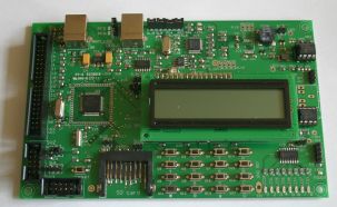
When the board is configured as hu_armboard_v2 MicroKit is configured for Franc vd Bent's HU ARM board version 2:

This board has
|
an NXP LPC2106 chip with a 10 MHz crystal |
|
parallel-port wiggler hardware (DB25F connector) |
|
an USB A (!) connector for power (the data lines are not connected) |
|
a DB9F serial connector for downloading and communication (connected to the UART0 TxD and RxD pins) |
|
two jumpers to enable LPC reset and bootload using handshake lines |
|
8 LEDs (connected to an HC595 shift register) |
|
a 1 line by 16 character LCD |
|
a 16-key keypad (connected to two HC165 shift registers) |
|
a small beeper/speaker |
|
a 40-pin extension connector |
|
two jumpers to select RUN, JTAG, or bootload mode |
More information about this board can be found on Franc's website (select ARM environment; Dutch language only).
When this board is specified the following defaults are active:
|
These defaults can be overruled by explicit definitions. As an example, one course on our school uses this board, but with a two-line LCD instead of the standard one-line version. The configuration used for this course is:
|
The board has two jumpers at the upper righthand side. The upper jumper (marked S1) controls whether bootload mode will be activated at reset: top position (marked 2) for bootload mode. The lower jumper (marked S2) controls whether the JTAG interface is enabled: top position (marked 1) enables the JTAG.
For JTAG operation both jumpers must be in their middle position (marked 1 for both jumpers), as indicated on the silkscreen in the lower left area.
For ROM downloading both jumpers must be in their top position (S1 in in position 2, S2 in position 1), and the reset key (bottom left) must be pressed. (When you forgot to press the reset you can in most cases press it when the download tool is trying to synchronise with the target.) The downloaded code will sometimes run after the download, but not always.
To let the code in ROM run upon powerup or reset the jumpers must be in the JTAG position: both in position 1.
|
When the board is configured as hu_armboard_v3 MicroKit is configured for Franc vd Bent's HU ARM board version 3:
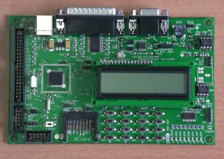
This board has
|
an NXP LPC2148 chip with 12 MHz and 32.768 crystals |
|
parallel-port wiggler hardware (DB25F connector) |
|
an USB connector for power; the data lines of this connector are connected to the LPC2148 USB pins |
|
a DB9F serial connector for downloading and communication (connected to the UART0 TxD and RxD pins) |
|
two jumpers to enable LPC reset and bootload using handshake lines |
|
8 LEDs (connected to an HC595 shift register) |
|
a 1 line by 16 character LCD |
|
a 16-key keypad (via a PIC 16F630 microcontroller) |
|
an SD-card connector |
|
one 40-pin and two 8-pin extension connectors |
|
two jumpers to select RUN, JTAG, or bootload mode (?) |
More information about this board can be found on Franc's website (select ARM environment; Dutch language only).
When this board is specified the following defaults are active:
|
These defaults can be overruled by explicit definitions.
This board has two jumpers at the upper righthand side. The upper jumper (marked S1) controls whether bootload mode will be activated at reset: top position (marked 2) for bootload mode. The lower jumper (marked S2) controls whether the JTAG interface is enabled: top position (marked 1) enables the JTAG.
For JTAG operation both jumpers must be in their middle position (marked 1 for both jumpers), as indicated on the silkscreen in the lower left area.
For ROM downloading both jumpers must be in their top position (S1 in in position 2, S2 in position 1). The downloaded code will sometimes run after the download, but not always.
To let the code in ROM run upon powerup or reset the jumpers must be in the JTAG position: both in position 1.
|
When the board is configured as hu_armboard_v4 MicroKit is configured for Franc vd Bent's HU ARM board version 4:
This board has
|
an NXP LPC2148 chip with 12 MHz and 32.768 crystals |
|
an USB connector for debugging, serial communication and serial downloading using an FT2232 interface chip (the serial interface is connected to the UART0 TxD and RxD pins) |
|
an USB connector for power; the data lines of this connector are connected to the LPC2148 USB pins |
|
a DB9F serial connector for downloading and communication (connected to |
|
two jumpers to enable LPC reset and bootload using handshake lines |
|
8 LEDs (connected to an HC595 shift register) |
|
a 1 line by 16 character LCD |
|
a 16-key keypad (via a PIC 16F630 microcontroller) |
|
an SD-card connector |
|
one 40-pin and two 8-pin extension connectors |
|
two jumpers to select RUN, JTAG, or bootload mode (?) |
More information about this board can be found on Franc's website (select ARM environment; Dutch language only).
When this board is specified the following defaults are active:
|
These defaults can be overruled by an explicit configuration.
This board has two jumpers at the upper righthand side. The upper jumper (marked S1) controls whether bootload mode will be activated at reset: top position (marked 2) for bootload mode. The lower jumper (marked S2) controls whether the JTAG interface is enabled: top position (marked 1) enables the JTAG.
For JTAG operation both jumpers must be in their middle position (marked 1 for both jumpers), as indicated on the silkscreen in the lower left area.
For ROM downloading both jumpers must be in their top position (S1 in in position 2, S2 in position 1). The downloaded code will sometimes run after the download, but not always.
To let the code in ROM run upon powerup or reset the jumpers must be in the JTAG position: both in position 1.
|
When the board is configured as keil_mcb MicroKit is configured for the Keil MCB2130 board:

This board has
|
an NXP LPC2148 chip with 12 MHz and 32.768 kHz crystals |
|
an USB connector for power (the data pins are not connected) |
|
two DB9F serial connectors for downloading and communication, connected to the two UARTs. The one connected to UART0 has the hardware for LPC reset and bootload using handshake lines Two jumpers activate this hardware. |
|
8 LEDs (connected to ARM pins via an 74LVC244 buffer) |
|
a small loudspeaker (connected to an ARM pin via an LM386 amplifier) |
|
a trim potentiometer, connected to an ARM A/D pin |
|
a reset button and a button that is connected to a reset pin |
|
a connector for a wall-wart (5V DC) |
|
an ARM-standard 20-pin JTAG connector |
|
a small 8 x 12 hole prototype area |
When this board is specified the following defaults are active:
|
These defaults can be overruled by explicit definitions.
|
When the board is configured as olimex_p2148 MicroKit is configured for the Olimex P2148 board:
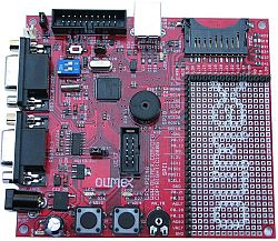
This board has
|
an NXP LPC2148 chip with 12 MHz and 32.768 kHz crystals |
|
an USB connector for power; the data lines of this connector are connected to the LPC2148 USB pins |
|
two DB9F serial connectors for downloading and communication, connected to the two UARTs. The one connected to UART0 has the hardware for LPC reset and bootload using handshake lines Two mini switches activate this hardware. |
|
2 LEDs (connected directly to ARM pins) |
|
a buzzer (small loudspeaker, connected directly to two ARM pins) |
|
a trim potentiometer, connected to an ARM A/D pin |
|
a reset button and a button that is connected to a reset pin |
|
a connector for a wall-wart (6-9V AC or 8-12V DC) |
|
an ARM-standard 20-pin JTAG connector |
|
a 10-pin Olimex UEXT extension connector |
|
a trim potentiometer, connected to an ARM A/D pin |
|
pin headers for all ARM I/O pins |
|
a 14 x 27 hole prototype area |
When this board is specified the following defaults are active:
|
These defaults can be overruled by explicit definitions.
A serial download to an LPC chip requires that the chip is reset, and the bootload enable pin is held low when the chip leaves reset. By convention these two functions can be controlled by two serial port handshake lines. By default it is assumed that your hardware supports this convention. If not, you will be asked to reset the chip and force it to enter bootload mode by hand (probably using switches or jumpers on your board).
In order to download code to an LPC ARM chip using the serial bootloader available in these chips the chip must be reset, and when it leaves reset it must find pin P0.14 high. Most boards that have a serial connector implement this function. For a hands-off download the reset and P0.14 pins can be controlled by the serial port handshake lines DTR and RTS. The circuit below is the standard circuit for this, as shown in the NXP documentation:
The flash-magic documentation shows a different circuit to achieve the same effect:
Note that this use of the handshake lines can cause trouble when a PC application that wants to communicate with your ARM board indavertently toggles the DTR line, causing a reset of the board. Most boards offer a way to disable the reset and bootload-enable functions of the handshake lines, often by removing one or two jumpers.
This introduction is specific to assmbler as used in MicroKit:
|
AS, the GNU assembler |
|
used for the ARM |
|
with the assembler-with-preprocessor option enabled |
Other assemblers and/or assemblers for different chips will differ in details.
The instruction set described here is the ARM7TDI-S instruction set, as used in the popular LPC chips. Newer ARM chips can handle these instructions, but might support a few more.
Assembler is a line-oriented programming language: basically each line is translated by itself, and generates zero or more values that are to be placed in memory at what is called the current location, after which the current location is incremented so it points to the next (free) location. Where exactly the values are placed in the chip's memory is up to the linker: the assembler writer does not know and should not care. If he needs to use the address where something is placed he can use a label (explained below).
Each line generates value(s) for a specific section. The three important sections are TEXT, BSS and DATA:
|
The TEXT section is for machine instructions and read-only data. When running from ROM the TEXT section will be placed in ROM. |
|
The BSS section is for data that does not need a specific initial value. When running from ROM the BSS section is placed in RAM. The startup code (supplied automatically) clears the BSS section (all memory locations are filled with 0). |
|
The DATA section is for read-write data that needs a specific initial value. When running from ROM the DATA section itself is placed in RAM, but a copy of the initial values is stored in ROM. The startup code copies these initial values from ROM to RAM. |
When running from RAM the distinction between TEXT and DATA is lost. The BSS segment is still initialized with 0 before your application starts.
An at-sign '@' or a slash-slash '//' starts a comment. That sign and the rest of the line is ingnored. C-style block comments (start with '/*', end with '*/") are also ignored. All other C preprocessor constructs (#define, #if, #include, etc) are also supported too. Lines that are empty (after removing comments) are ignored.
When the first word on a line has a colon ':' after it that word is the definition of a label. Such a word can be used in the assembler program (both after its definition and - unlike C - also before its definition) and will then be replaced by the address of the 'current location' at the place of the label. In practice this means that it is the address of the next 'thing' following the label in your program. Labels are case-sensitive. The convention is that labels start in the first column, and assembler instructions and directives do not.
Constant values can be expressed in a number of ways:
|
Labels: a label name is replaced by the corresponding memory location. |
|
Expressions: all C operators (+,-,*,%,/,<<, >>,&,|,^, etc) can be used to build more complex expressions from literal values and labled names. |
Except for comments and labels each non-empty line contains either an ARM instruction or an assembler directive. Directives start with a point '.', assembler instructions start with a letter. De most important directives are:
|
.global : This directive must be followed by a (comma separated) list of labels. By default assembler labels are visible only in the file in which they are defined. The labels mentioned in a .global directive are visible to all other files in the project. |
|
.byte : This directive is followed by a (comma separated) list of values. The values are placed in sucessive memory locations, occupying one byte each. |
|
.word : This directive is like the .byte directive, but each value occupies a word (4 bytes) |
|
.ascii : This directive is followed by a double-quote delimited string. Each letter of this string is placed in a successive memory location. |
|
.asciz : This directive is like the .ascii directive, but an extra 0 byte is added at the end of the string of bytes. |
|
.align : This directive skips as many memory locations as required to make the memory address (where the next item will be placed) a multiple of 4. |
|
.skip : This directive is followd by a number. It skips that number of memory locations. |
|
.arm : These directives indicates that, untill specified otherwise, the following assembler instructions are ARM (not Thumb) instructions. |
|
.code : This directive indicates that, until specified otherwise, the following lines are to be placed in the CODE section. |
|
.data : This directive indicates that, until specified otherwise, the following lines are to be placed in the DATA section. |
|
.bss : This directive indicates that, until specified otherwise, the following lines are to be placed in the BSS section. |
The ARM chip has 16 register, R0 ... R15. Each register is 32 bits wide. R0 .. R12 are general-purpose registers that can be used by the application in any way it likes (but the C compiler can use R8 for a specific purpose). Registers R13, R14 and R15 have a special purpose. They are preferrably used by their alternate names: SP, LR and PC. SP is the Stack Pointer, PC is the Program Counter, LR is the Link Register.
Each ARM assembler instruction is 32 bits (1 word, 4 bytes). Instructions must start on an address that is a multiple of 4. What happens when you don't align instructions is not defined. The LPC chips seems to reset when an unaligned instruction is executed.
In most ARM instruction the information (data) flows from right to left, just like in a C assignment statement. The STR and STM instructions are the exceptions: in these instructions the data flows from left to right.
There is no single instruction to load a constant 32-bit value into a register (why not?). Instead the assembler offers a fake instruction that translates into an assembler instruction and a data word. The format of this instruction is
|
The register can be any of the registers R0 .. R15, or one of the alternate register names SP, LR, PC. The value can be any constant expression.
The ARM is a register-register architecture: there is a strict separation between instructions that do calculations, and instructions that do memory access. The memory access instructions can load a 1, 2 or 4 byte value into a register, or store such a value from a register into a memory location. The format of these instructions is
|
The destination, source and address must be registers. The s is an optional size specification: it can be B for a byte, H for a half-word (2 bytes) or omitted for a word (4 bytes). For a word load or store the address must be a multiple of 4, for a half-word it must be a multiple of 2. What happends wghen you load or store to an unaligned address is not defined. On LPC chips such a load can (often?) produce the 'correct' result.
When a byte or a half-word is stored the higher bits in the source register are ignored. When a byte or half-word is loaded the remaining bits in the register are filled with copies of the highest loaded bit. This is called sign extension: it preserves the 2s-complement value.
There are 3 variations of the load and store instructions. The first one adds an offset to the address register (without changing the address in the register):
|
The second variation is like the first one but with an exclamation mark after the instruction. The effect is that the offset is added to the address register (thus updating the address register), and this new address register value is used as address:
|
The third variation first uses the addres that is in the address register, and after that it adds an increment (a constant value) to that addres register:
|
The offset or increment must be a constant expression.
The load (and store) *multiple* instructions can read or write a set of registers in one instruction. The address of the memory region is supplied by (another) register. This register can contain either the highest of the used addresses (hence the successive addresses that are used will be decending) or the lowest (ascending). Additionally, the address register can contain either the first address to be used, or one step beyond the first location. Combining this with loading and storing this produces 8 variations: LDM or STM for load or store, E or F for Empty or Full, D or A for Descending or Ascending: LDMFD, LDMED, LDMFA, LEMEA, STMFD, STMED, STMFA, LEMEA.
These load and store multiple instructions are mostly used to implement a stack. The convention is to use a stack that grows down (from a high memory address to lower memory addresses), and to have a stack pointer in R13 (hence its name SP) that points to the lowest memory location that is in use (Full). Hence the assembler mnemonics that are commonly used are STMFD and LDMFD.
The B (branch) instruction is what other processors call a jump or a goto: it causes the execution of instructions to continue at the label after the B. The BL (branch and link) instruction is what other processors call the call or gosub:
To Be Written: B, BL, conditions, LR trick, arithmetic, S