IR-3 : low-cost IR decoder with 10 outputs
|
|
IR-3 : low-cost IR decoder with 10 outputs |
|
The IR-3 is an IR decoder for the RC5, Sharp and TC101 protocols. The IR-3 provides 10 decoded outputs, that by default respond to the buttons 0..9 on any of the supported IR remotes, but can be re-configured to specific keys of specific remotes. The outputs are by default active high, so a driver chip like ULN2803 can be interfaced directly, but can be re-configured to active-low. An IR receiver like a TSOP must be used to receive the IR signal.
The IR-3 is available as chip ($PRODUCT-PP-IR3), or as kit ($PRODUCT-K-IR3) with a PCB and all components. The TSOP1736 IR receiver is recommended for RC5 (Philips, 36 kHz signal), the TSOP1738 is recommended for Sharp and TC101 (38 kHz signal). The TSOP1737 is recommended when both 36 kHz and 38 kHz signals must be received. The kit contains a TSOP1737.
In practive each of these receivers can be used with each frequency, but the range might be smaller than when the receiver is matched to the IR frequency.
The pinout of the IR-3 chip is shown below. It is actually a programmed 16F630 microcontroller.
| +5 Volt | 1 | 14 | ground | ||
| IR signal/configure (out/in) | 2 | 13 | (out) button 1 | ||
| button 0 (out) | 3 | 12 | (out) button 2 | ||
| IR input (in) | 4 | 11 | (out) button 3 | ||
| button 9 (out) | 5 | 10 | (out) button 4 | ||
| button 8 (out) | 6 | 9 | (out) button 5 | ||
| button 7 (out) | 7 | 8 | (out) button 6 |
The ground and +5 Volt pins must be decoupled with a 100nF capacitor close to the pins. The IR input signal must be active low, as produced by a standard encapsulated IR receiver like the TSOP17xx series. All button outputs are default active high, but can be re-configured to active-low. The IR signal output will be active (high) when an IR signal is present on the IR input, irrespective of whether this signal is recognised as a valid IR message. The inactive state of this pin is high-impedance (input). This pin must be pulled low by a resistor (1..50k) during normal operation, it must be connected to + 5 Volt during power-up to enter configuring mode (see below). While the IR signal for one of the buttons 0..9 (or when configured: one of the configured buttons) is received the corresponding output will be active while the signal is received.
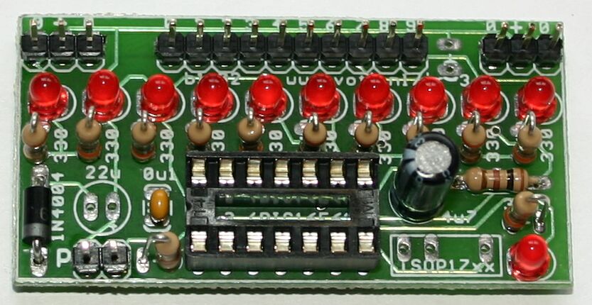
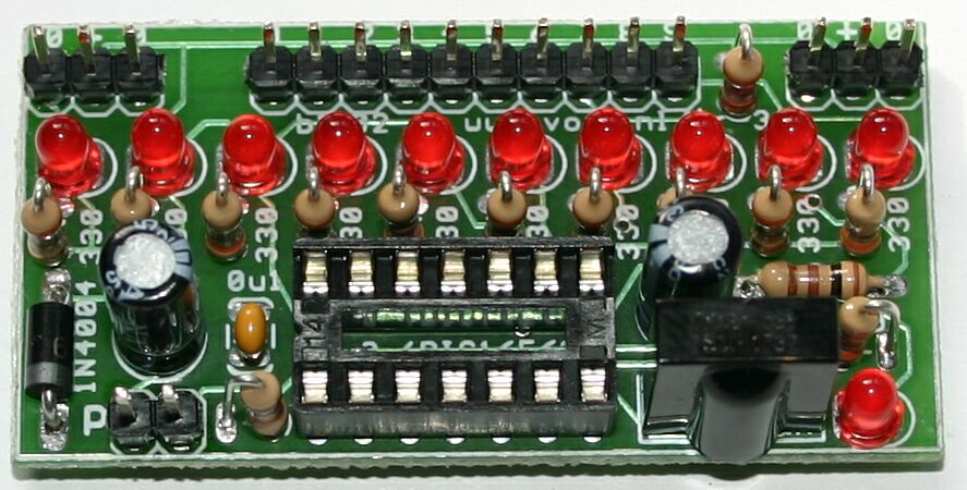
A circuit than can be used with the IR-3 chip is shown below. Click on the image for a bigger one.
The circuit consist of
| two connectors for the power (one can be used to receive power, one to supply power to the circuit that is controlled), a fools diode to limit the damage when +5 Volt is applied the wrong way round, 22 uF and 100 nF decoupling |
| the IR-3 chip itself |
| a TSOP IR receiver with a resistor and capacitor as recommended by the manuafacturer |
| a pin header (CON4) for selecting configuring mode (resistor R13 keeps the chip in non-configure mode when no jumper is fitted on the header) |
| 10 LEDs LED1 .. LED10 (with series resistors) to indicate the state of the 10 outputs |
| one LED LED11 to indicate that an IR signal is received |
| 10 pads for connecting the circuit(s) to be controlled |
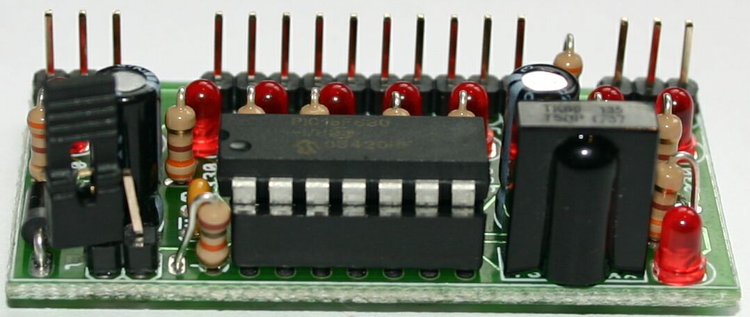
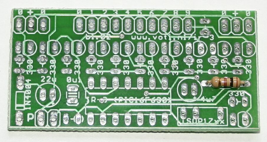
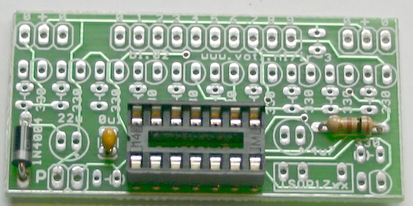
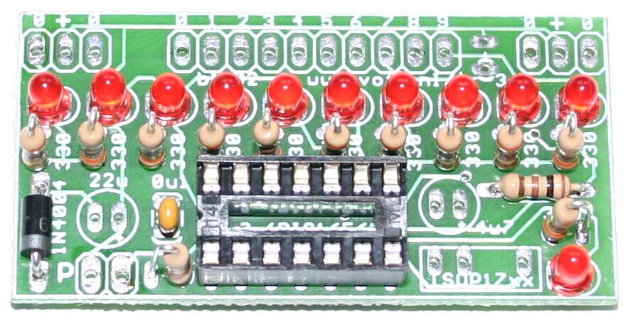
This kit is small but the components are closely packed on the PCB, so it requires carefull assembly, using the step-by-step instructions below. Take care to put the components in the correct orientation, as shown on the pictures. You can click on most pictures to get a larger one.
| The description assumes that you have the board oriented as shown, the with solder pads at the top and the chips (PIC and IR receiver) at the bottom. |

|
|
| Place and solder the 100 &Omega resistor (brown-black-brown). |
|
|
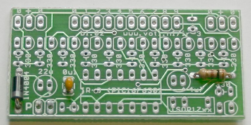
| Place and solder the 1N4004 or 1N5819 diode. Watch the orientation: the white band on the diode must match the band on the silkscreen. |

|
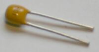
| Place and solder the 100 nF capacitor. It is marked as "104". |
|
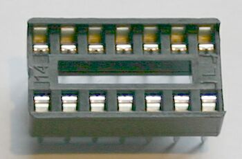
| Place and solder the IC socket. The notch must be at the left side. |
|
|
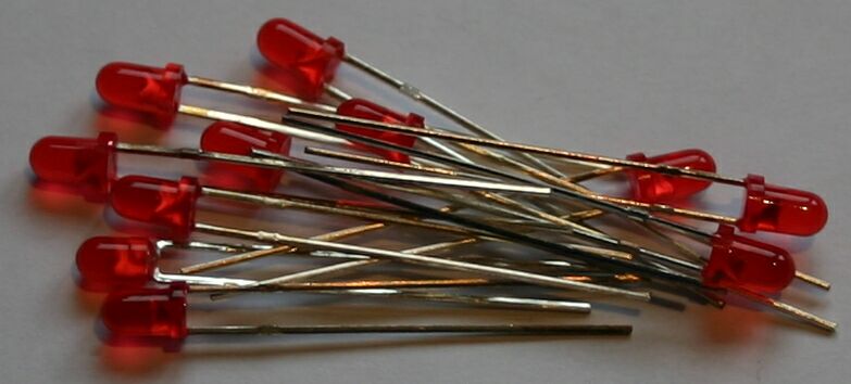
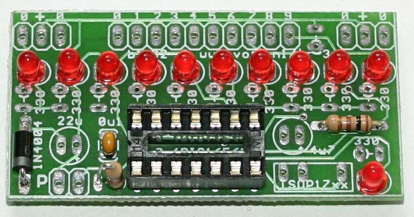
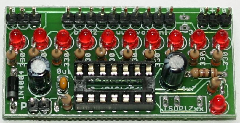
Place and solder the LEDs: 10 in a row in the middle of the PCB, one on the lower-right side.
Take care to orient the LEDs correctly: the longer wire must be inserted in the hole inside the white
marking.
If you have cut the wires: the flat part of the LED surface must be aligned with
the flat side of the white marking.
My way to solder the LEDs is first to use cellotape to hold them in place. Next solder the longer wire of each LED. Now look very carefull at the row of LEDs, and re-solder or bend them untill they are perfectly aligned. Any misalignment will show very clear when the receiver is used, and this is your chance to correct it. When the LEDs are aligned solder (and cut) the other wires. |

|
|
| Place and solder the 10 k&Omega resistor (brown-black-orange). It must be mounted vertically, to the left of the IC socket. The PCB version b1.01 (check the solder side) has no value marking for this resistor. |
|
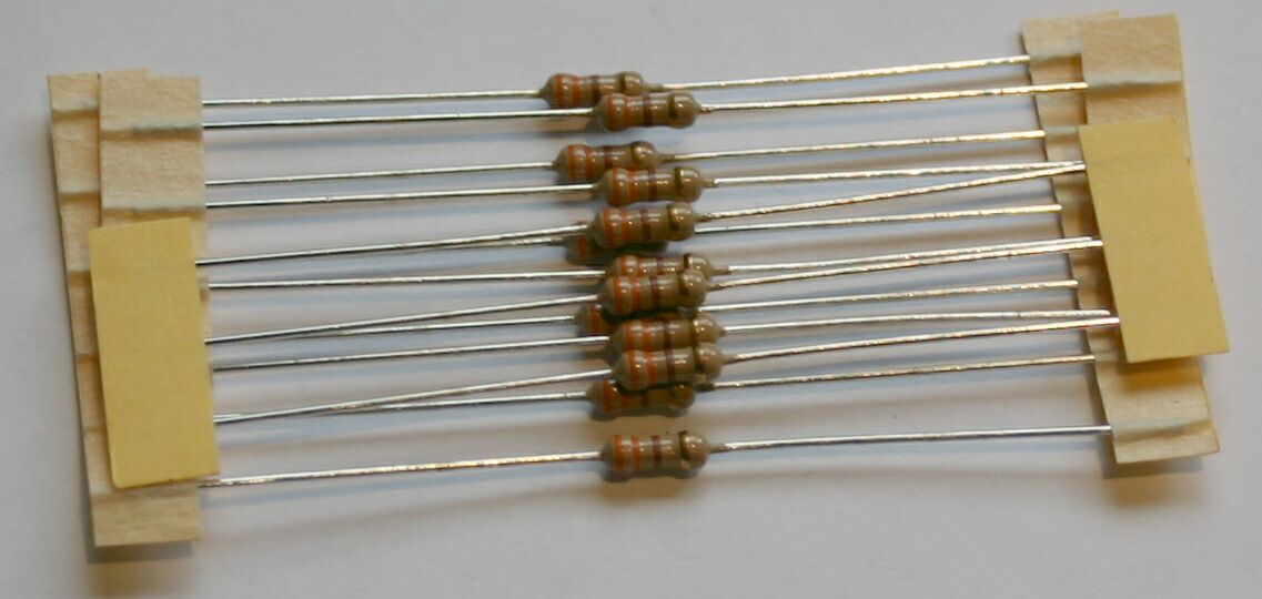
| Place and solder the 12 330 &Omega resistors: 10 in a row in the middle of the PCB, one at the lower right side, one at the upper right side (between the solder pad rows). Note: this last resistor is not shown on the picture! These resistors are all mounted vertically. |
|
|
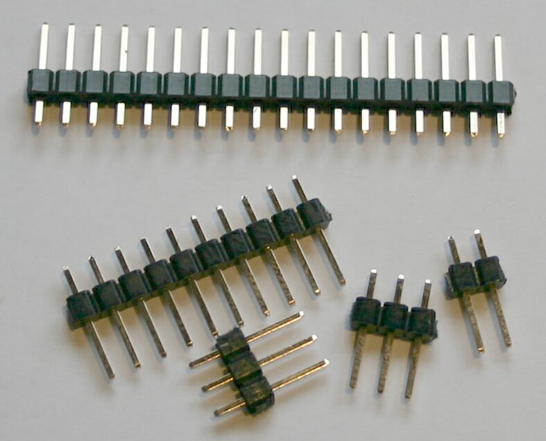
If you want to connect to your IR receiver in a different way (not using pin strips) you
should solder only the 2 pin header.
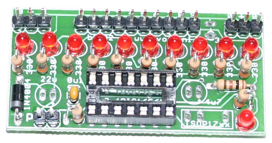
Cut the 18 pin header strip in 4 parts: 2, 3, 3 and 10 pins. Place and solder the various strips. |
|
| Place and solder the 4.7 uF capacitor. The longer wirte must be at the right side, the white stripe on the capacitor at the left side (towards the DIP sovket). |
|
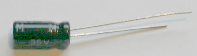
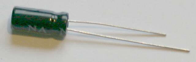
| Place and solder the 22 uF capacitor. |
|
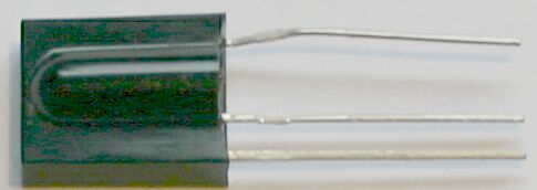
| Place and solder the TSOP1737 IR receiver. |
|
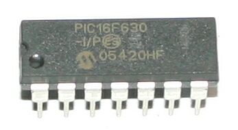
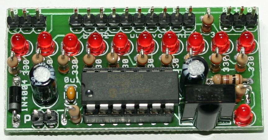
| Place the 16F630 IR decoder chip. The dot must be at the lower-left side. |
|

| If you want to configure the receiver: place the jumper. If not: keep it somewhere so you can find it if you ever want to configure the receiver. You could put the jumper over one pin. |

|
Connect 5V to one of the two power pins headers: +5V to the middle pin, ground to (one or both) outer pins. Your power supply should be short-circuit protected and not deliver more than 1A. When you connect the power the wrong way the 1N4004 or 1N5819 diode in the IR receiver will short the power.
Immediately after you connect the power the receive LED (the one next to the IR receiver) should blink twice. If it does not there is some problem with your circuit or the +5V power.
Aim your IR remote at the IR receiver and press one of the keys. The receive LED (next to the IR receiver) should be on or blink while you press the key. If it does not your circuit is not OK or your IR remote does not work (or it works at a very non-standard frequency).
Aim your IR remote at the IR receiver and press one of the keys 0..9 (or one of the keys you have configured). The corresponding output LED (one of the LEDs in the row) should be on or toggle when you press the key. If it does not your but the IR receive LED does blink you probably have an IR remote that is not supported. Try another IR remote.
If the IR receiver responds to the IR remote in the intended way (probably after configuring the receiver, see below) you can connect your external circuit(s) to the output pins (or solder pads). Note that these outputs connect directly to PIC pins, so you will probably need an appropriate buffer to control your circuit. An ULN2803 can be used to driver relays or low-current lamps. Logic-level MOSFETs can be used to switch higher-current loads (a series resistor of 1k is recommended).
As delivered the IR-3 chip is configured to respond the the keys 0..9 of an RC5, Sharp or TC101 (NEC) IR remote controller. When this suits your needs you can skip this section.
The IR-3 chip is put into configure mode by connecting pin 2 (IR signal/configure) to pin 1 (+5 Volt) and then apply the +5 Volt to the chip. For the kit: place the jumper and apply power. The circuit shown on this page has a connector CON4 (pinheader) for this purpose. Note that when your circuit contains a larger capacitor (the circuit on this page shows a 22uF capacitor) you must remove power for at least 10 seconds to be sure that the chip is realy powered down, before re-applying the power.
When the IR-3 chip powers up in configure mode it first restores the default setting (respond to keys 0..9 of RC5, Sharp and TC101 remotes). If you want this setting you can now remove the power, remove the connection between pins 1 and 2, apply power and start using the chip.
When you want to configure the IR-3 chip to respond to specific keys you can now point your remote controller at the chip and press the 10 keys the chip must respond to. While configuring the output that will be configured next is active (when the circuit shown on this page is used: the LED is on). When 10 keys have been configured the last output will reset to inactive. You can now remove the power, remove the connection between pins 1 and 2, apply power and start using the chip.
By default the outputs of the IR-3 chip are active high. You can configure the outputs to active-low by pressing the same key twice during configuring.
The protocols recognised by the IR-3 chip are as described on the following webpages:
| Philips RC5 protocol : http://www.xs4all.nl/~sbp/knowledge/ir/rc5.htm (but LSB/MSB is wrong), or http://users.pandora.be/nenya/electronics/rc5/ |
| Sharp (SIRCS?) protocol : http://www.xs4all.nl/~sbp/knowledge/ir/sharp.htm |
| NEC TC101 protocol : http://www.xs4all.nl/~sbp/knowledge/ir/nec.htm |
Some other IR protocol links:
| A general discussion about IR protocols: http://www.users.bigpond.com/pbhandary/pic/iralyze/sig_analysis.html |
| An ITT protocol: http://www.xs4all.nl/~sbp/knowledge/ir/itt.htm |
Information about the PIC16F630 can be found at http://www.microchip.com/1010/pline/picmicro/category/embctrl/8kbytes/devices/16f630/index.htm.
Information about the TSOP 17xx IR receivers can be found at http://www.vishay.com/docs/82030/82030.pdf.
http://www.voti.nl/ir-3
Copyright (c) 2003, 2004 Van Ooijen Technische Informatica / Wouter van Ooijen