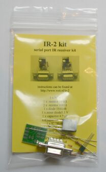
IR-2 : a low-cost PC serial port IR receiver
Purpose
Circuit
Assembly - default
Assembly - alternate
Software and links
|
|
IR-2 : a low-cost PC serial port IR receiver
Purpose
|
|
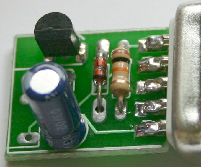
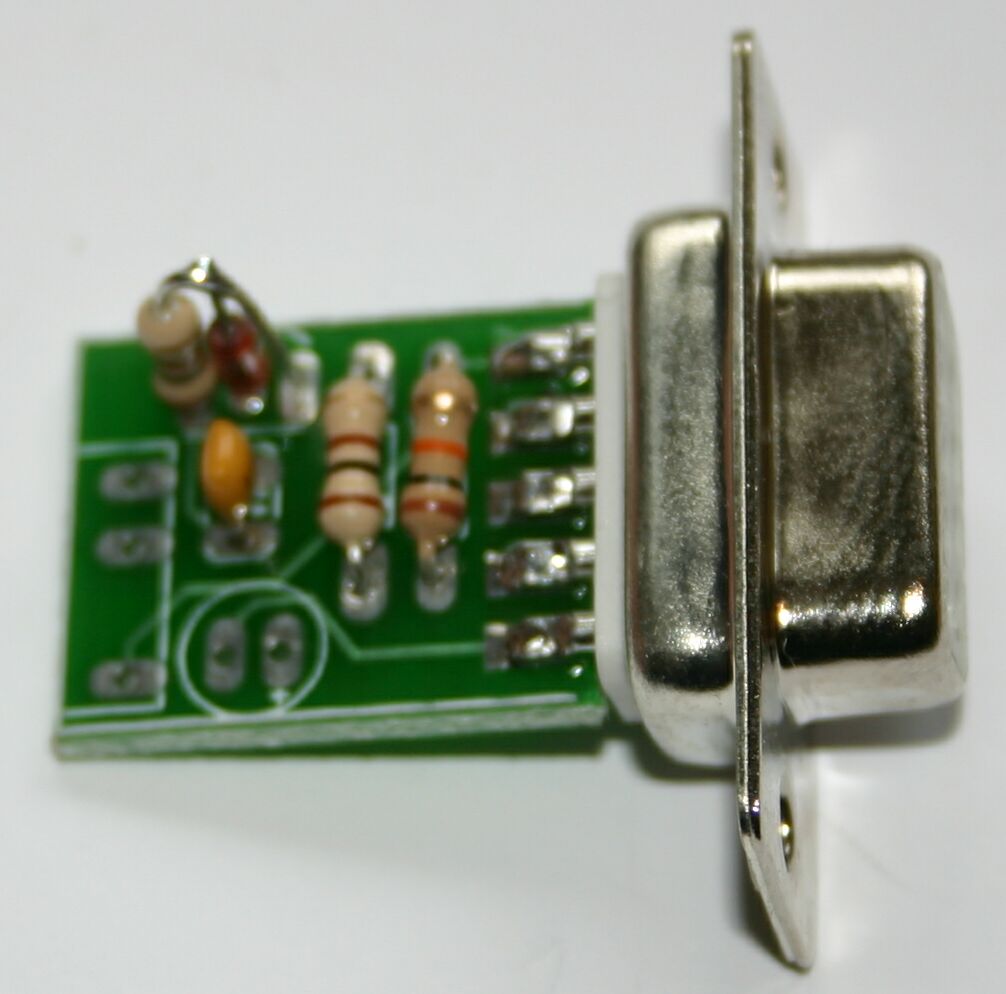
The IR-2 is a cheap IR receiver for the PC serial (RS-232) port. IR-2 is compatible with common PC programs like LIRC (Linux) and WINLIRC (Windows). With the appropriate software this allows you to control your PC using a IR remote control.
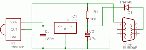
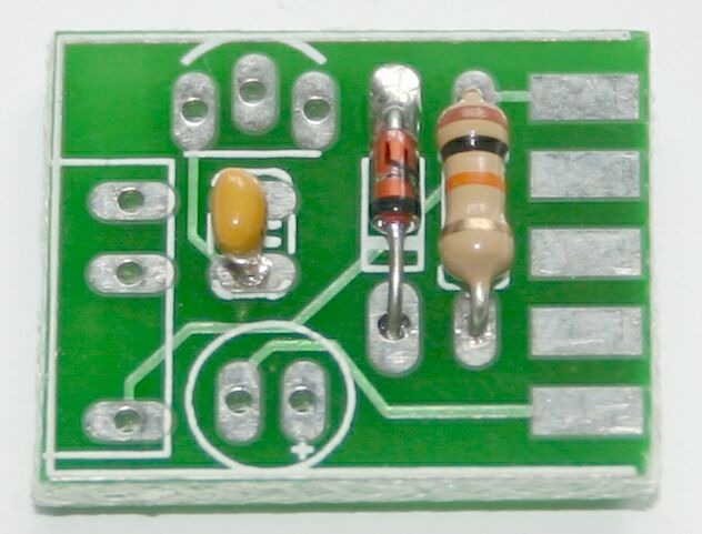
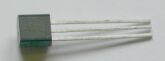
The default circuit is very simple. Pin 7 of the serial port (RTS) provides power, which is stabilised by D1, C2 and IC1. IC2 is the IR receiver itself, any TSOP17xx receiver can be used. The kit contains a TSOP1737, which is a compromise between the two common carrier frequencies (36 kHz and 38 kHz). The output of the IR receiver is fed back to pin 1 (DCD) of the serial port, with a pull-up provided by R1.
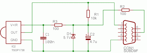
When the voltage provided by the serial port is not high enough for the default circuit (laptops often output a lower voltage) the above alternate circuit can be used. The kit contains components for both. The alternate circuit uses R2 and D1 (a zender diode) to reduce the voltage to 5 Volt. This circuit will work on all serial ports that output at least 5 Volt, but the default circuit is better when the serial port outputs at least 9 Volt.
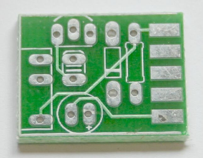
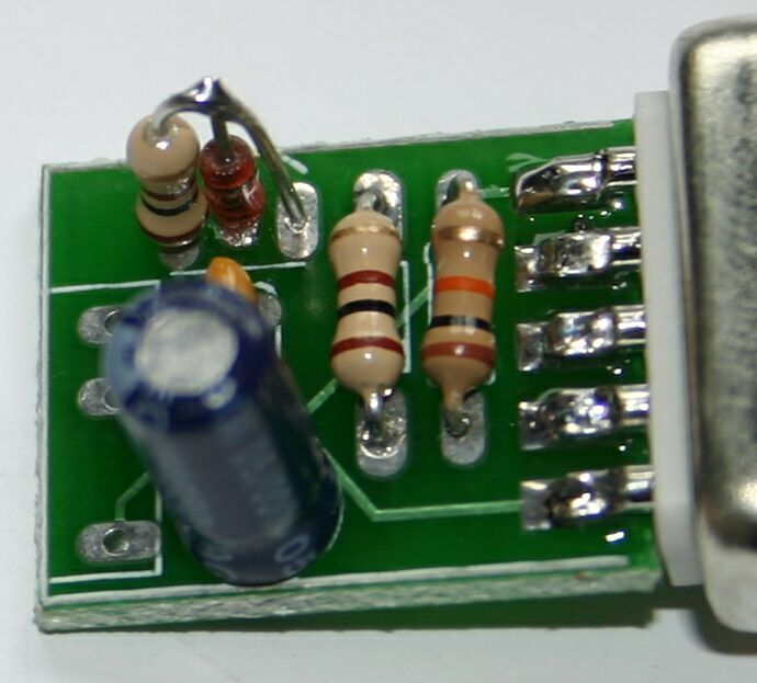
This kit is small but the components are closely packed on the PCB, so it requires carefull assembly, using the step-by-step instructions below. Take care to put the components in the correct orientation, as shown on the pictures. You can click on most pictures to get a larger one.
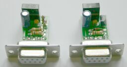
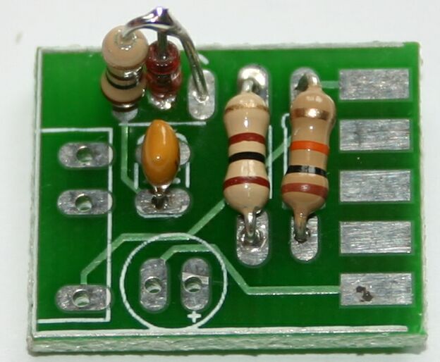
The IR-2 can be assembled in two versions, default and alternate. The kit contains the components for both versions. For the default version the zener diode and the two 100 Ohm resistors (brown-black-brown) are not used.
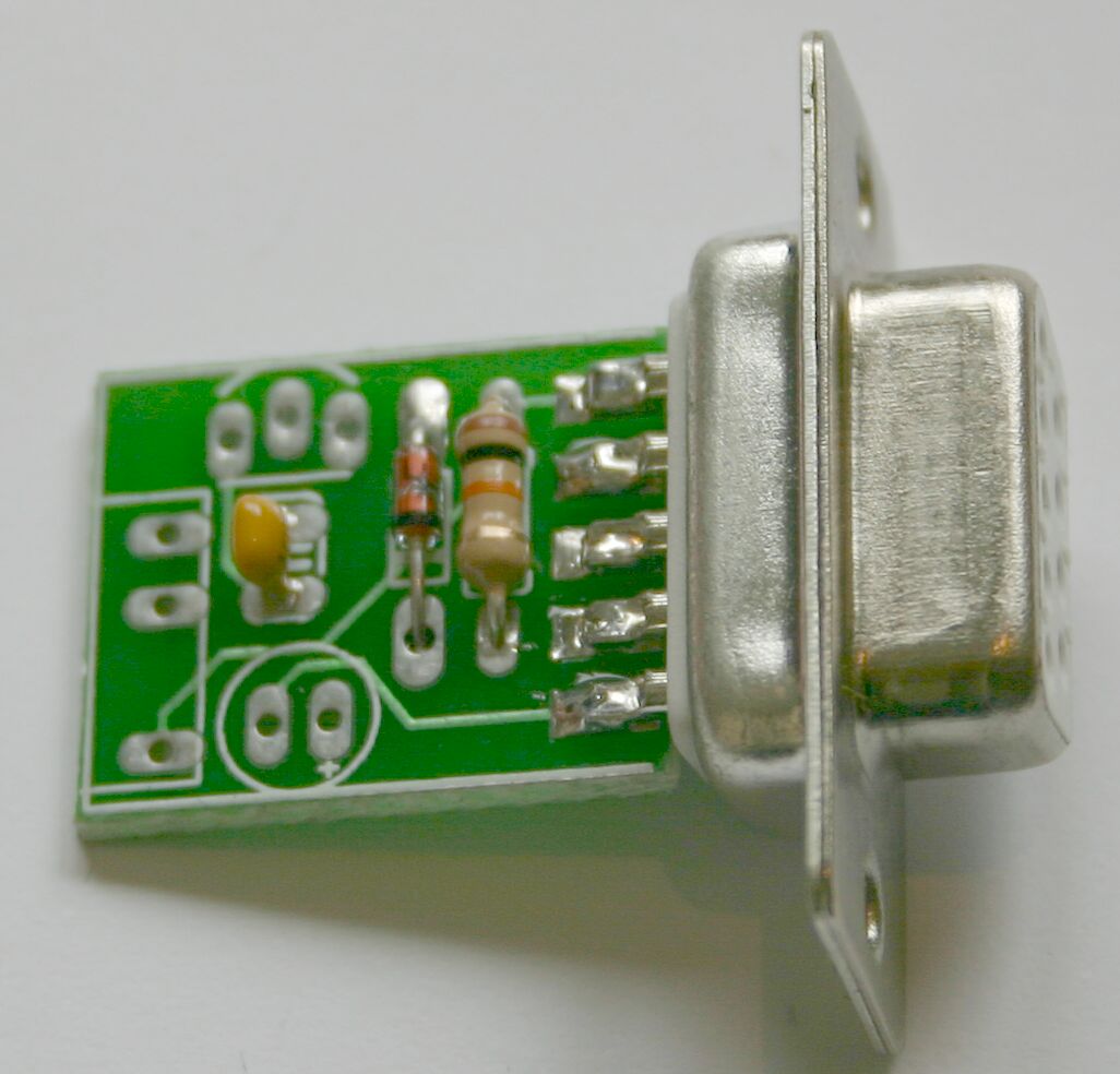
| The description assumes that you have the board oriented as shown, the with the pads for the DB9 connector to the right. |
| |
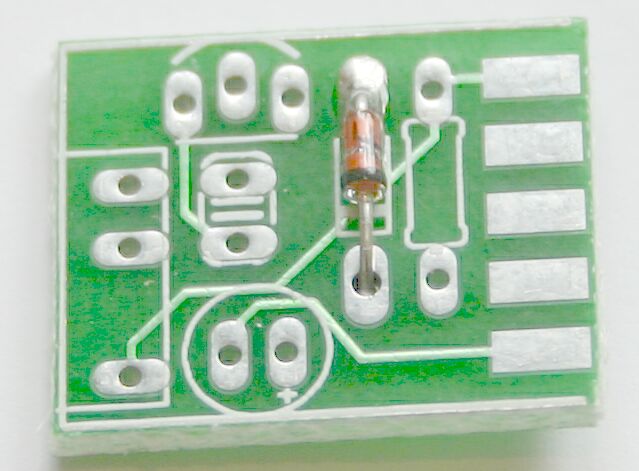
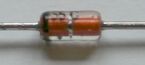
| Place and solder the 1N4148 diode. Watch the orientation: the white band on the diode must match the band on the silkscreen. |
|
|
| Place and solder the 10k resistor (brown-black-orange). |
|
|
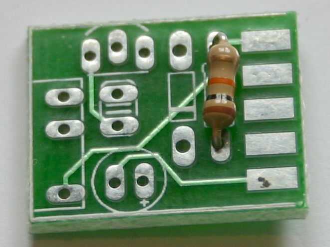
| Place and solder the 100nF capacitor. It is marked as "104". |
|
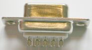
| Place and solder (both copper side and component side) the DB9 connector. |
|
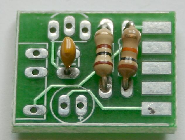
| Place and solder IC1 (78L05). The flat side must be oriented away from the edge of the PCB. |

|
|
| Place and solder the 4.7 uF capacitor C1. The white stripe must be oriented away from the DB9 connector. |
|
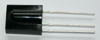
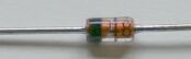
| Place and solder the TSOP1737 IC2. |

|
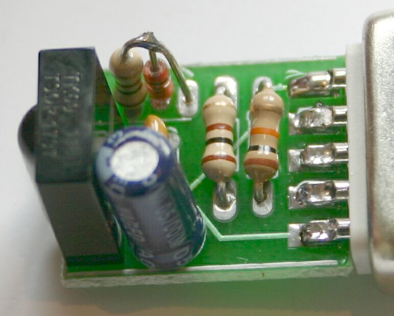
This kit is small but the components are closely packed on the PCB, so it requires carefull assembly, using the step-by-step instructions below. Take care to put the components in the correct orientation, as shown on the pictures. You can click on most pictures to get a larger one.
The IR-2 can be assembled in two versions, default and alternate. The kit contains the components for both versions. For the alternate version the 1N4148 diode and IC 78L05 are not used.
| The description assumes that you have the board oriented as shown, the with the pads for the DB9 connector to the right. |
| |
|
| Place and solder the 10k resistor (brown-black-orange). |
|
|
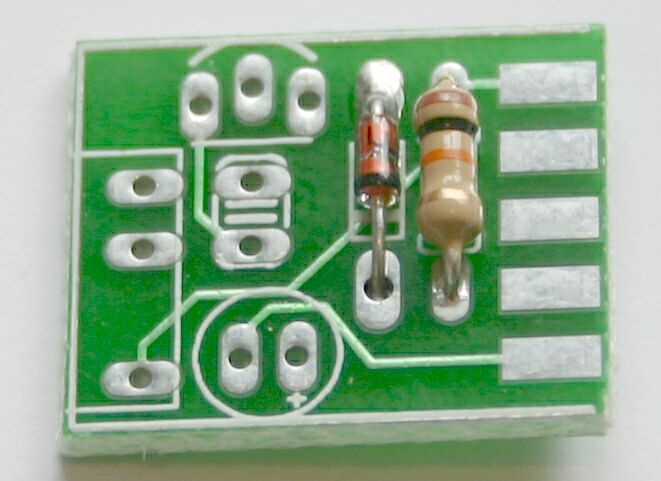
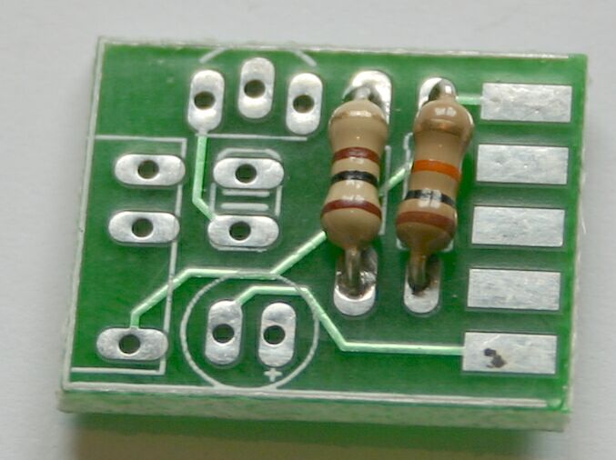
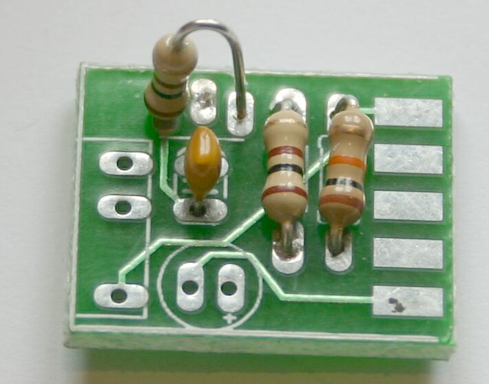
| Place and solder one of the 100 Ohm resistors (brown-black-brown). |
|
|
| Place and solder the 100nF capacitor. It is marked as "104". |
|
|
| Place and solder the second 100 Ohm resistor (brown-black-brown) as shown. The resistor itself must be in the left hole, the 'flying' leg must be in the right hole. |
|
| Place and solder the 5.1 V zener diode. The black band side must be connected to the 'flying' leg of the 100 Ohm resistor, the other side must be inserted and soldered in to the middle hole. |
|
|
| Place and solder the 4.7 uF capacitor C1. The white stripe must be oriented away from the DB9 connector. |
|
|
| Place and solder (both copper side and component side) the DB9 connector. |
|
|
| Place and solder the TSOP1737 IC2. |
|
| LIRC is the standard Linux software for receiving IR signals |
| WINLIRC is the Windows port of LIRC |
http://www.voti.nl/ir-2
Copyright (c) 2004 Van Ooijen Technische Informatica / Wouter van Ooijen